Getting Started
Problem Statement
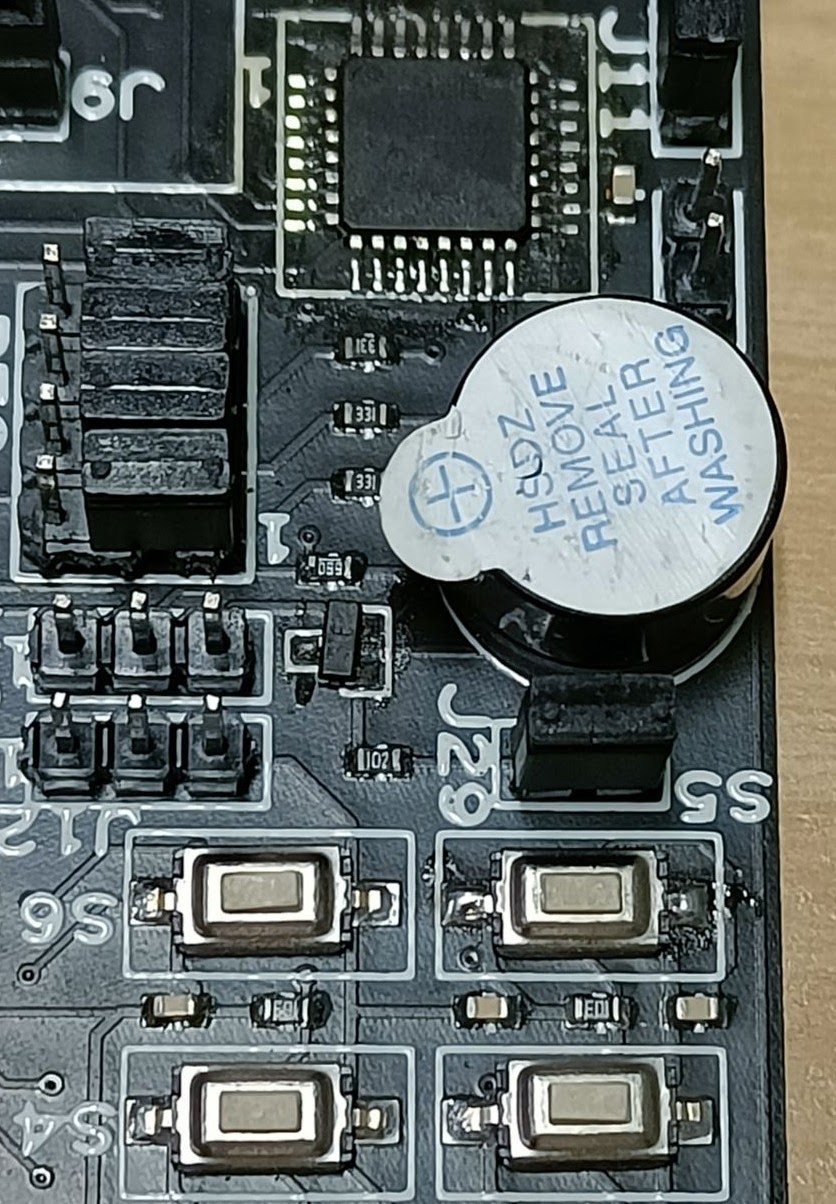
For our first program, we will play with the buzzer, which is already interfaced with the Atmega2560 Development Board. Make sure that jumper J29 is connected. The following picture shows how the jumper is connected and where it is located.
Working
- Buzzer connection with Atmega2560
- Buzzer : PH2
- Download Buzzer.c by clicking the hyperlink which will redirect you to the GitHub. You can then download the code from there.
The following code is present in the Buzzer.c file:
c
// Crystal Frequency of Atmega2560
#ifndef F_CPU
#define F_CPU 16000000UL // set the CPU clock
#endif
#include <avr/io.h>     // Standard AVR IO Library
#include <util/delay.h> // Standard AVR Delay Library

int main(void)
{
    DDRH = 0XFF; // Initialize buzzer pin PH2 as output
    while (1)
    {
        PORTH = 0x00; // Turn ON the buzzer
        _delay_ms(1000);
        PORTH = 0xFF; // Turn OFF the buzzer
        _delay_ms(1000);
    }
}- Open a terminal in VS Code using Terminal > New Terminal, or just use the shortcut " Ctrl + Shift + ` " ( where ` is the back quote key). Type the following command in the terminal to generate the Buzzer.hex file:
cmd
avr-gcc -Wall -g -Os -mmcu=atmega2560 -o Buzzer.hex Buzzer.c- You will see Buzzer.hex file generated in the same folder where Buzzer.c file is present.
- The next step is to flash the hex file into the microcontroller. To do so we will use USBASP and follow the steps given below:
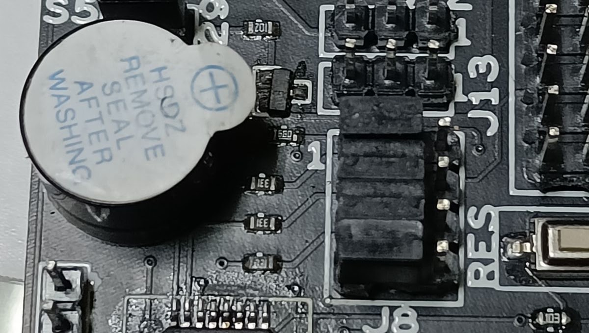
- Make sure that the jumper J8 position is as shown below to select USBASP:
Burning hex file
- Connect Micro USB Cable at J7 (Flip the board, you will see "USBASP" written in the board)
- Open AVRDUDESS software by double-clicking on the executable in windows and for Ubuntu users run the following command where executable is present:
cmd
mono avrdudess.exe- From the Programmer (-c) dropdown, select Any usbasp clone with correct VID/PID
- From the MCU (-p) first select 'ATMega2560' and directly click on Detect which will automatically select the board details. After the above two steps, your screen should look like the following image.

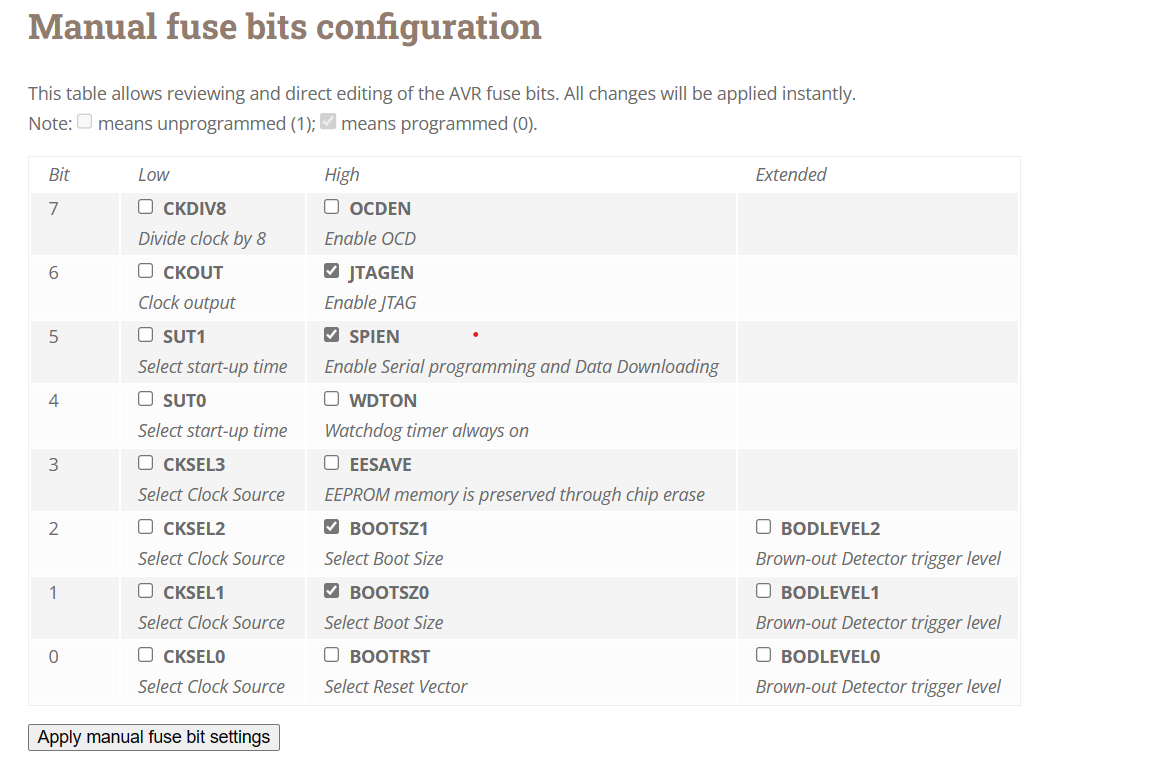
- Set fuse and lock bits according to the clock you are using, for 16 MHz the Low fuse bit is "0xFF" and the High fuse bit is "0x99"
- To program a bit, set it to "0" and to reset it assign "1".
- Refer to this fuse calculator guide for AVR controllers.
- From the Flash section, click on three dots and navigate to the Buzzer.hex file, and select it.
- Check the "write" button shown in the following image.
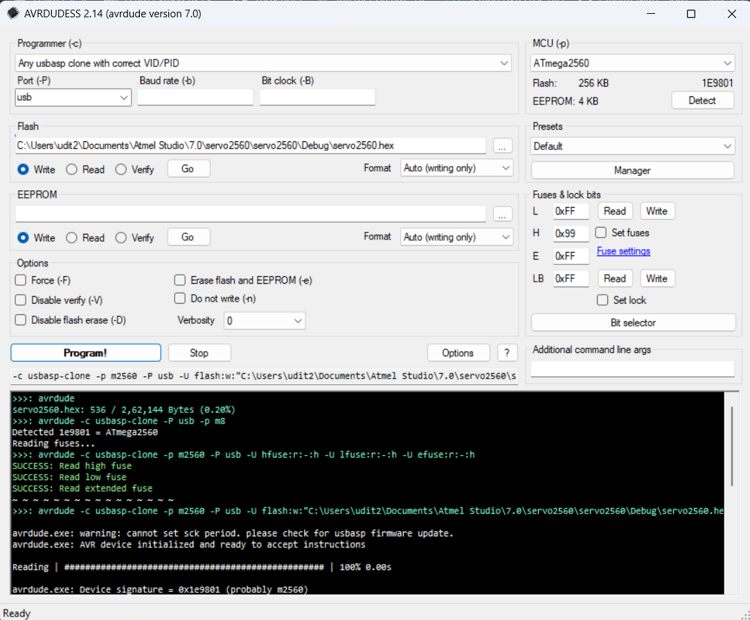
- Finally, click on Program to burn the hex file in the microcontroller. You'll see the above output in AVRDUDESS and the buzzer should start beeping.