Interfacing encoder and interrupt with ESP32
Introduction
This guide provides instructions on how to interface an encoder with an ESP32 microcontroller using interrupts. The encoder generates pulses as it rotates, allowing us to track the position and direction of rotation. By counting these pulses, we can monitor the movement of the encoder and perform actions based on the changes in its position.
Problem Statement
The objective of this project is to use interrupts to count the encoder value on the ESP32 microcontroller.
Requirements
To successfully complete this project, you will need the following components:
- ESP32 development board
- Photoelectric Speed Sensor
- Encoder Coded Disc
- Jumper wires
Circuit Diagram
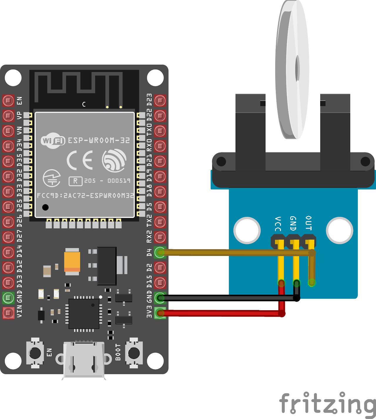
Follow the circuit diagram below to connect the push button and led to the ESP32 development board:
- Connect the VCC pin of Photoelectric speed sensor to the 3v3 pin of ESP32.
- Connect the data pin on the sensor to GPIO 4 (D4) of the ESP32 and GND of sensor to GND of ESP32.
Code
Now let's understand and write the C code to check for interrupt. Follow the steps below:
Open VS Code and create a new sample project with the name encoder_interrupt (Follow previous guides to see how to do it).
Now navigate to the "Main" folder of the project and then open the Main.c file.
Copy and paste the following code into Main.c or download the code from here:
#include <stdio.h>
#include "freertos/FreeRTOS.h"
#include "freertos/task.h"
#include "freertos/queue.h"
#include "driver/gpio.h"

/*

********************************************************************************

ESP32 GPIO Interrupts

If encoder wheel rotates, the count will increase by 1 per slot on disc.

********************************************************************************/

#define ENCODER_PIN GPIO_NUM_4
#define ESP_INTR_FLAG_DEFAULT 0

static QueueHandle_t gpio_evt_queue = NULL;
long long int count = 0;
static void IRAM_ATTR button_isr_handler(void *arg)
{
    uint32_t gpio_num = (uint32_t)arg;
    xQueueSendFromISR(gpio_evt_queue, &gpio_num, NULL); // Send the ISR's gpio_num argument to the queue
}

static void encoder_task(void *arg)
{
    //
    while (true)
    {
        // Wait for a GPIO event
        uint32_t gpio_num;
        if (xQueueReceive(gpio_evt_queue, &gpio_num, portMAX_DELAY)) // Wait indefinitely for the next encoder change event
        {
            count++; // Increment the counter
            printf("Count: %lld\n", count);
        }
    }
}

void app_main()
{
    gpio_config_t io_conf;

    // Configure the enocder pin as input with pull-up resistor
    io_conf.intr_type = GPIO_INTR_NEGEDGE;
    io_conf.mode = GPIO_MODE_INPUT;
    io_conf.pin_bit_mask = (1ULL << ENCODER_PIN);
    io_conf.pull_up_en = GPIO_PULLUP_ENABLE;
    gpio_config(&io_conf);

    // Create a queue to handle button events
    gpio_evt_queue = xQueueCreate(10, sizeof(uint32_t));
    if (gpio_evt_queue == NULL)
    {
        printf("Failed to create GPIO event queue\n");
        return;
    }

    // Configure and install the ISR (Interrupt Service Routine)
    gpio_install_isr_service(ESP_INTR_FLAG_DEFAULT);
    gpio_isr_handler_add(ENCODER_PIN, button_isr_handler, (void *)ENCODER_PIN); // Pass the encoder pin number as an argument

    // Create a task to handle encode events
    xTaskCreate(encoder_task, "encoder_task", 2048, NULL, 5, NULL); // Higher priority than the LED task
    while (true)
    {
        vTaskDelay(10 / portTICK_PERIOD_MS);
    }
}- Now at the bottom navbar of VS Code select the port, flash method and click on the Build, flash and monitor icon.
Note: During the flashing process of your board, you may encounter an error. If this happens, there's no need to worry. Simply flash the board again and when you see the message "connecting..........." appear, press and hold the boot button on your board for 1 or 2 seconds. Keep holding it until the dots on the screen start disappearing or the further flashing process begins. This action will help resolve any issues and ensure a successful flashing of your board.
Output
Upon successful flashing and proper connections, the system initializes and starts counting the slots changed upon rotation of the encoder wheel.
The count value is continuously printed to the serial monitor whenever a pulse is detected. Rotate the encoder shaft to observe changes in the count value. Each rotation or movement of the encoder generates pulses, resulting in a change in the count value.
Conclusion
By following this guide, you have successfully interfaced an encoder with an ESP32 microcontroller using interrupts. You have learned how to track the position and movement of the encoder by counting the pulses generated. This knowledge can be applied to various applications such as motor control, robotic systems, and position sensing, which can be used to control robots and cars precisely.