Interfacing Switches with ATmega2560 Development Board
Introduction
This guide will demonstrate how to interface switches with the ATmega2560 development board. The board has six built-in switches connected to pins on ports "D" and "E" of the ATmega2560 microcontroller. By following the steps outlined in this guide, you will be able to read the state of the switches and incorporate them into your projects.
Problem Statement
The goal is to read the state of the switches connected to pins on ports "D" and "E" of the ATmega2560 and perform actions based on their states. This will allow you to take user input from the switches and utilize it in your embedded systems projects.
Requirements
To successfully complete this project, you will need the following components:
- ATmega2560 development board.
- Micro USB cable
- Push button switches (built-in)
Working
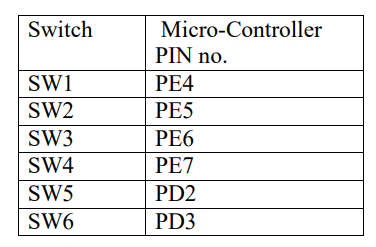
- Six switches are connected to the development board as follows:
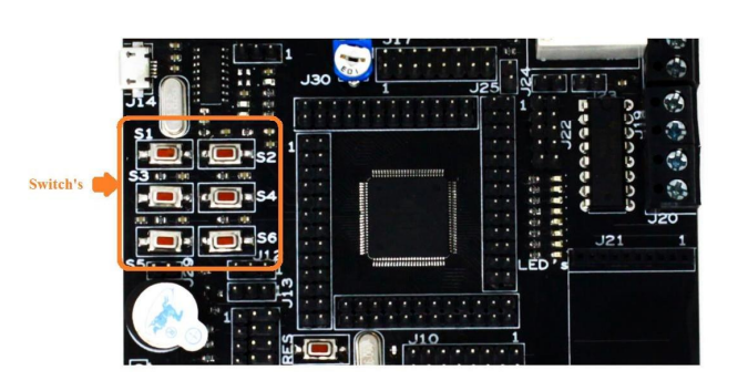
- When you press, the logic “LOW” appears on the respective pin; otherwise, the PIN will be “HIGH”.
- 8 LED are connected to development board as follows:
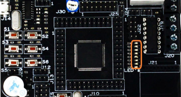
- When the push button "S1" is pressed, the corresponding LED on port "C" is turned on.
Circuit Connections
Code
- Open VS Code and paste the code into the file named switch_led.c
- To compile and convert the source code into hex, run the following command in your terminal-
avr-gcc -Wall -g -Os -mmcu=atmega2560 -o switch_led.hex switch_led.cYou can download the code from here.
#ifndef F_CPU
#define F_CPU 16000000UL // set the CPU clock
#endif
#include <avr/io.h>
#include <util/delay.h>

int main(void)
{
    DDRC = DDRC | (1 << 0); // Makes PORTC0 as Output
    DDRE = DDRE & (~1 << 4); // Makes of PORTE4 as Input

    while (1) // infinite loop
    {
        if (bit_is_clear(PINE, 4))
        {
            PORTC = PORTC & (~1 << 0); // HIGH ON PORTC.0
        }
        else if (bit_is_set(PINE, 4))
        {
            PORTC = PORTC | (1 << 0); // LOW ON PORTC.0
        }
    }
}- Now open AVRDUDES and from the Programmer (-c) dropdown select Any usbasp clone with the correct VID/PID
- In the Flash section, click on three dots and navigate to the desired hex file, and select it. Finally, click on Program to burn the hex file in the microcontroller
Output
Upon successful interfacing and code execution, the LCD module will display "Origami with electronics". You can use the custom functions to control the cursor, clear the display, and print characters or strings on the LCD. The contrast of the LCD can be adjusted using the potentiometer.
Conclusion
Interfacing an LCD with the ATmega2560 development board allows you to display information and create user interfaces for your projects. By following the steps outlined in this guide, you should be able to successfully interface the LCD module with the ATmega2560 and display desired content on the LCD screen