Interfacing ECG sensor with Raspberry Pi
Introduction
In this guide, we will delve into the realm of biometric sensing by exploring how to interface an ECG (Electrocardiogram) sensor with the Raspberry Pi 3B+. The ECG sensor allows us to capture and analyze the electrical activity of the heart, providing valuable insights into cardiac health. By leveraging the GPIO (General Purpose Input/Output) pins of the Raspberry Pi, we can establish a connection with the ECG sensor and acquire heart rate and rhythm data. With this information, we can create applications that monitor heart health, analyze ECG patterns, or trigger alerts based on abnormal cardiac activity. Follow along with this tutorial to unlock the potential of the Raspberry Pi in integrating an ECG sensor and embarking on exciting projects in the field of healthcare and wellness.
Problem Statement
The objective of this project is to get ECG sensor ADC values using AD8232.
Requirements
- Raspberry Pi
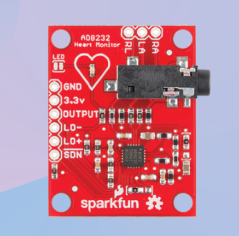
- AD8232 sensor
- MCP3008 IC
- Micro-USB cable
- Jumper wires
- Breadboard
Working
The ECG sensor can be utilized with a Raspberry Pi 3B+ to get ECG values and display the value on terminal.
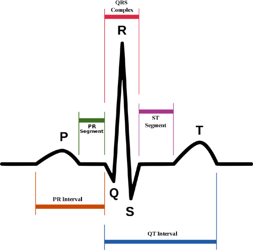
ECG or Electro Cardiography is a method to measure some important parameters of a human heart. It outputs analog values that produce a particular signal that looks as shown below.
Each interval of the signal has an optimal value range, and deviation from that might be linked to a particular disease. Here are the main parts of an ECG signal.
- P wave - It is the trailing wave on the left of the QRS complex.
- QRS complex - It is an impulse generated by ventricular contraction.
- T wave - It is a leading wave right to the QRS complex.
- U wave - It is not always observed due to its low peak value.
The values to plot this ECG graph is obtained.
Circuit Diagram
- Connect the VDD(PIN 16) of MCP-3008 to 3V3(Pin 1) of RPi
- Connect the VREF(PIN 15) of MCP-3008 to 3V3(Pin 17) of RPi
- Connect the AGND(PIN 14) of MCP-3008 to GND(Pin 6) of RPi
- Connect the CLK(PIN 13) of MCP-3008 to GPIO11(Pin 23-SCLK) of RPi
- Connect the DOUT(PIN 12) of MCP-3008 to GPIO9(Pin 21-MISO) of RPi
- Connect the DIN(PIN 11) of MCP-3008 to GPIO10(Pin 19-MOSI) of RPi
- Connect the SHDN(PIN 10) of MCP-3008 to GPIO8(Pin 24-CEO) of RPi
- Connect the DGND(PIN 9) of MCP-3008 to GND(Pin 34) of RPi
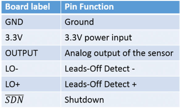
- Connect the CH0(PIN 1) of MCP-3008 to OUTPUT of sensor
- Connect same rail connected to 3V3 of RPi to VCC of sensor
- Connect same rail connected to GND of RPi to GND of sensor
- Connect the GPIO17 of RPi to LO- of sensor
- Connect the GPIO27 of RPi to LO+ of sensor Refer the Soil Moisture page for ADC MCP3008 connections with this link.
Code
Now let's write the Python code for obtaining ECG values. Follow the steps below:
- Connect to your Raspberry Pi using VNC or Desktop environment.
- Launch the Geany Python IDE or open a text editor to write the code.
- Create a new file named
ecgadcvalues.pyand save the following code into it - You can copy and paste the following code from here into the file.
py
import spidev
import time
import RPi.GPIO as GPIO
# import asciichartpy

# SPI device
spi = spidev.SpiDev()
spi.open(0, 0)  # Set the SPI port (bus 0, device 0)
spi.max_speed_hz = 1000000  # Set the SPI clock frequency (1 MHz)

# AD8232 pin configuration
AD8232_LO_POS_PIN = 17  # Leads off detection LO +
AD8232_LO_NEG_PIN = 27  # Leads off detection LO -

# GPIO setup
GPIO.setmode(GPIO.BCM)
GPIO.setup(AD8232_LO_POS_PIN, GPIO.IN)
GPIO.setup(AD8232_LO_NEG_PIN, GPIO.IN)

def read_adc(channel):

    # MCP3008 data format
    # 0x01 - Start bit
    # 0x80 - Single-ended mode, channel select (0 to 7)
    # 0x00 - Null bit
    adc_command = [0x01, (0x80 | channel) << 4, 0x00]
    adc_data = spi.xfer2(adc_command)
    adc_value = ((adc_data[1] & 0x03) << 8) + adc_data[2]  # 10-bit ADC value
    return adc_value

# Create empty lists for storing data
timestamps = []
adc_values = []

while True:
    try:
        # Read the leads off detection status
        lo_pos_status = GPIO.input(AD8232_LO_POS_PIN)
        lo_neg_status = GPIO.input(AD8232_LO_NEG_PIN)

        if lo_pos_status == 1 or lo_neg_status == 1:
            print("Leads off detection triggered!")
        else:
            # Read the raw ADC value from the AD8232 sensor
            # Assuming AD8232 is connected to channel 0
            adc_value = read_adc(0)
            print("VALUE: ", adc_value)

            # Perform any necessary calculations or processing with the ADC value
            # For example, you can convert it to voltage or perform some signal processing
            # Store the timestamp and ADC value in the lists
            timestamps.append(time.time())
            adc_values.append(adc_value)
            # Plot the ADC values on the terminal
        # Plot the ADC values
        # chart = asciichartpy.plot(adc_values, {'height': 10})
        # print(chart)
        time.sleep(0.5)  # Delay between reading

    except KeyboardInterrupt:
        break

# Cleanup
spi.close()
GPIO.cleanup()- After saving the file execute it by clicking on messenger like icon on geany editor or open terminal and navigate to the folder you saved the file, execute it by typing python
ecgadcvalues.py
Output
The ADC values from the ECG sensor will be displayed on the terminal.
Conclusion
By following this guide, you have acquired the knowledge to interface an ECG sensor with the Raspberry Pi and extract ADC (Analog-to-Digital Converter) values representing the electrical activity of the heart. You have successfully established a connection between the ECG sensor and the Raspberry Pi's GPIO pins, written the required code to capture and interpret the ADC values, and gained the ability to monitor heart rate and rhythm. This newfound capability opens up a world of possibilities for various applications in the realm of healthcare and wellness. You can now explore projects like real-time ECG monitoring systems, heart rate variability analysis, arrhythmia detection, or even integration with IoT platforms to enable remote cardiac health monitoring. The integration of an ECG sensor with the Raspberry Pi empowers you to embark on exciting ventures that contribute to personal health tracking and medical innovation. Let your imagination soar and leverage the potential of ECG sensor ADC values to make a positive impact in the field of biometric sensing and healthcare technology.