Controlling LED brightness using PWM with the STM32-F103RB Nucleo Board
Introduction
Problem Statement
Requirements
To successfully complete this project, you will need the following components:
- Nucleo-F103RB board
- LED
- Resistor (220-330 ohms)
- Jumper wires
- Breadboard
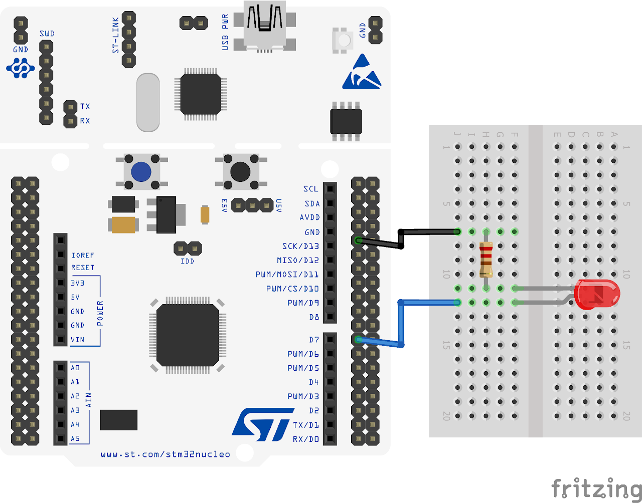
Circuit Diagram
Follow the circuit diagram below to connect the LED to the Nucleo board:
- Connect the anode (long leg) of the LED to PA8 of the Nucleo board.
- Connect the cathode (short leg) of the LED to a resistor (220 ohms).
- Now connect the other end of the resistor to the ground (GND) pin of the board.
Project Configuration
Follow these steps to configure the .IOC file and set up GPIOs and Clock :
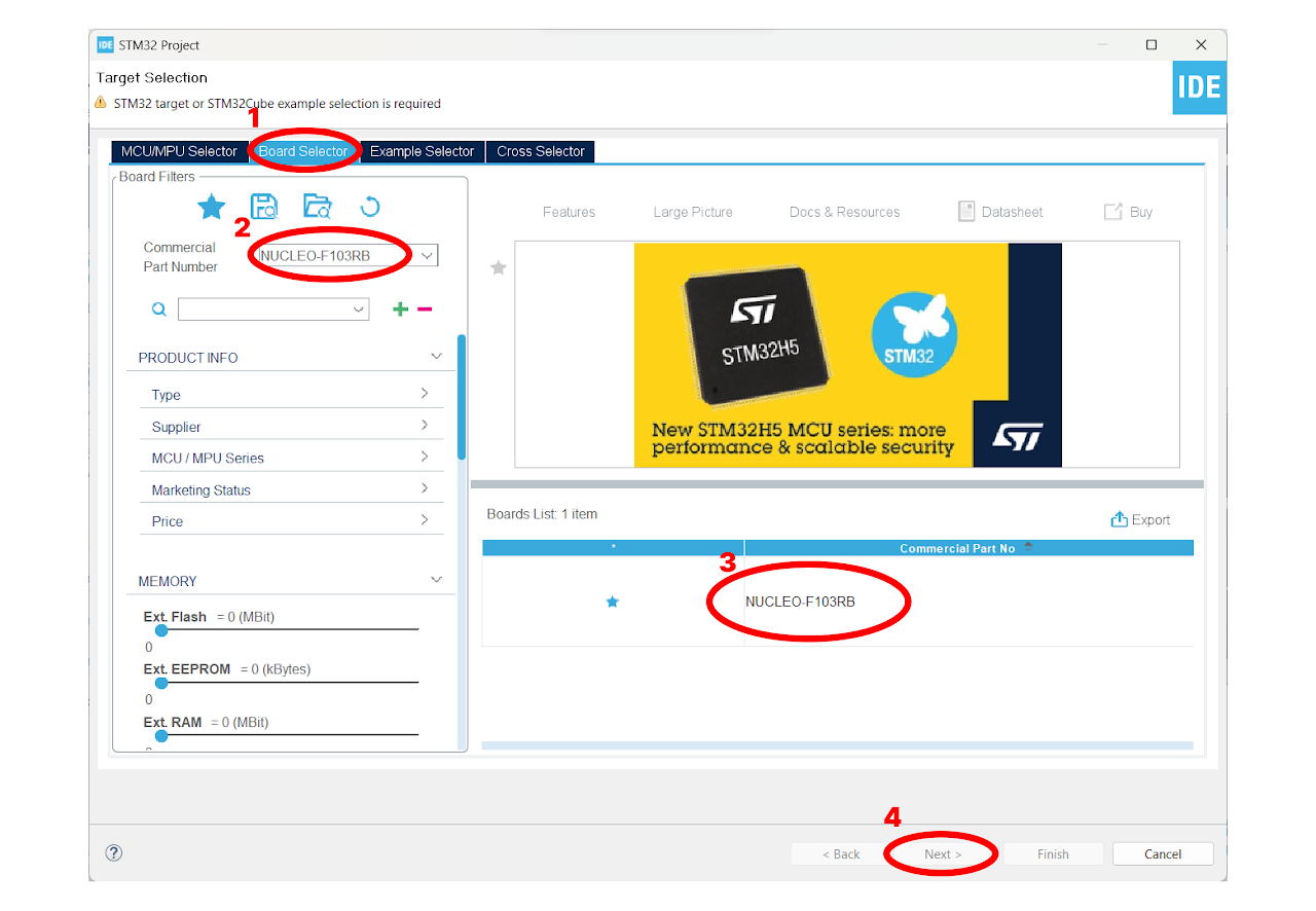
Open the STM32 Cube IDE and start by creating a new STM32 project. Click on the board selector tab in the target selection window.
Enter "NUCLEO-F103RB" as the commercial part number and click on "Next" after selecting the board.
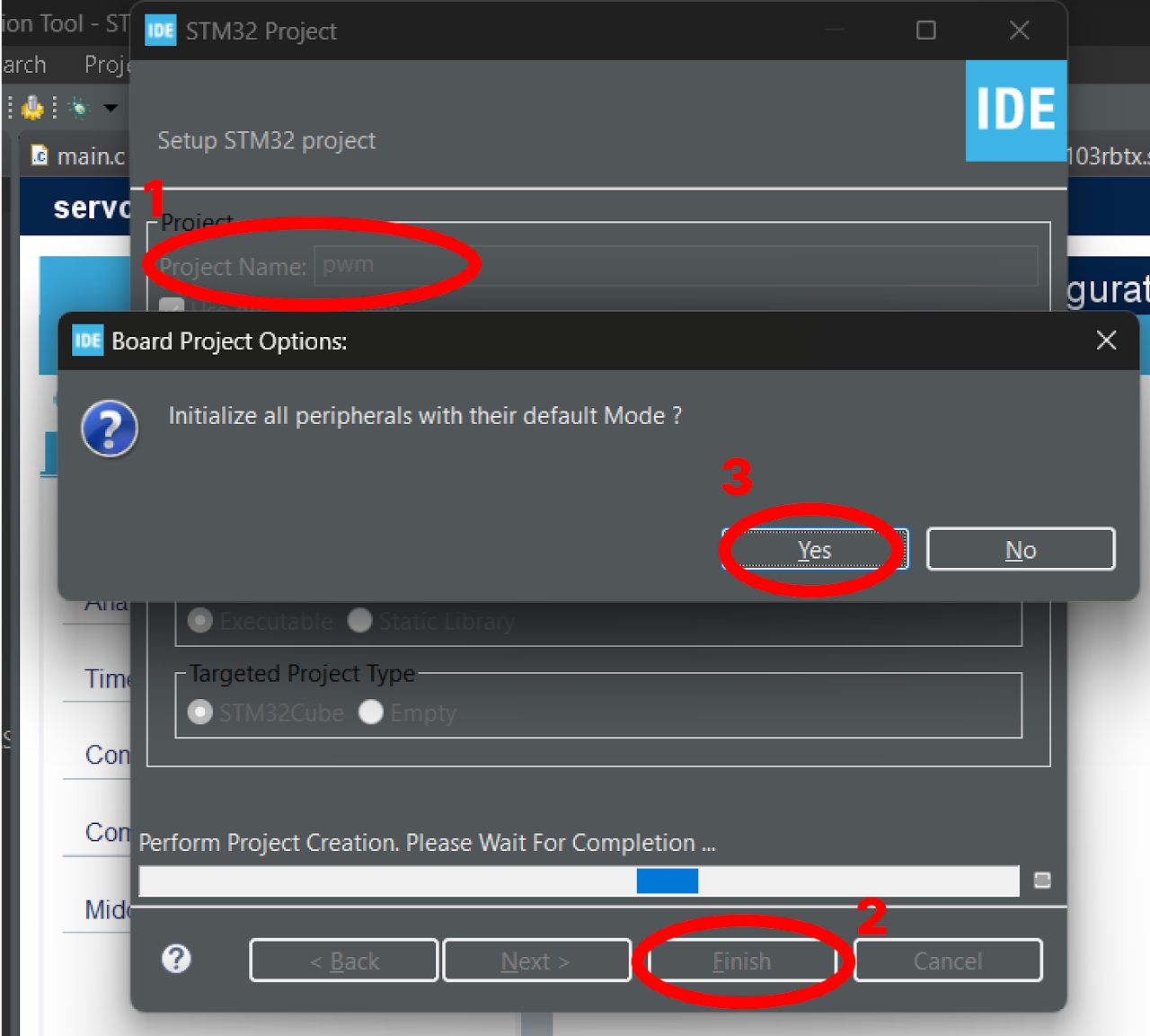
- Enter the Project Name "pwm_led" and click on "Finish". After that, click on "Yes" to initialize all the peripherals in default mode.
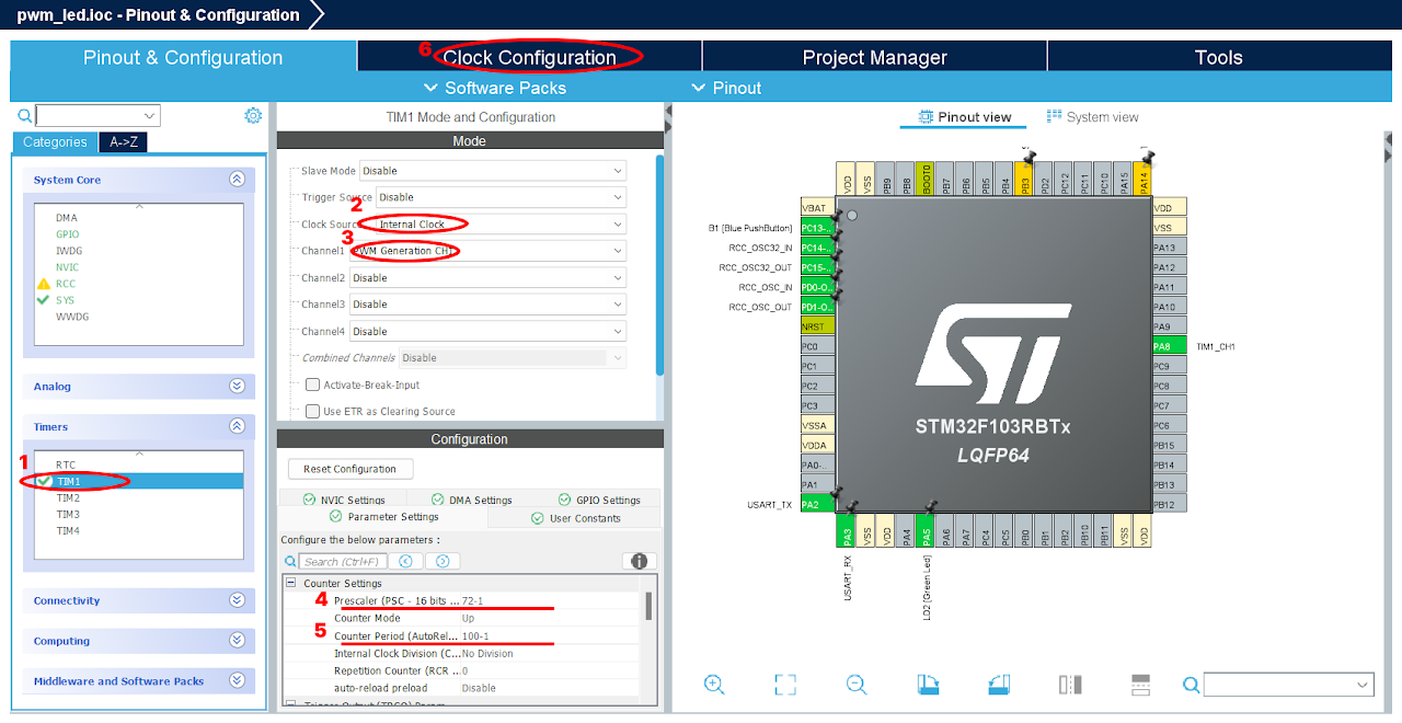
Pinout & Configuration: In the Pinout & Configuration menu, select "TIM1" from the Timers section. This will configure Timer 1 for generating PWM signals.
Clock Source and PWM Generation: Choose "Internal Clock" as the Clock Source to utilize the internal clock of the STM32-F103RB Nucleo Board for PWM generation. Additionally, select "PWM Generation CH1" in Channel 1. This setting enables PWM generation on channel 1, which corresponds to PA8 on the board.
Timer Configuration: In the Configuration part of the Timers section, set the Prescaler value as "72-1". The prescaler determines the frequency of the timer clock. Here, we divide the timer clock frequency by 72.
Next, specify the Counter Period as "100-1". The counter period defines the overall period of the PWM signal. With a value of 100-1, the PWM signal will complete one cycle every 100 timer clock cycles.
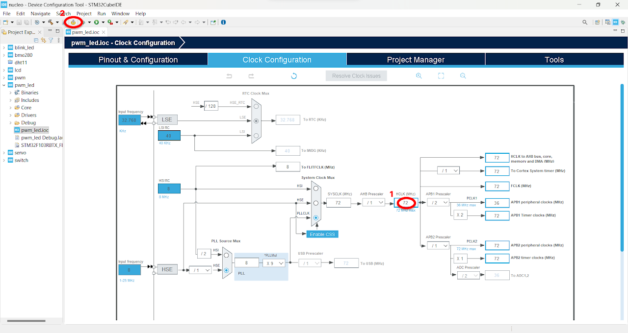
After finishing the Pinout Configuration, go to the Clock Configuration menu. In the HCLK field, enter "72 MHz" as the desired frequency for the HCLK (system clock). The Integrated Development Environment (IDE) will automatically search for the necessary clock sources and prescalers based on this configuration.
Next, locate the gear-like icon on the toolbar and click on it. This will add the configuration settings we did in the GUI to the code.
Code
Now, let's proceed to understand and write the C code to control the brightness of the LED. Follow the steps below:
The Device Configuration Tool will automatically open the main.c file for you. In the project, you will find all the necessary pin and port names defined in the Core ⇾ Inc ⇾ main.h file. These definitions will help us easily reference the pins and ports in our code.
Navigate to the main function in the main.c file and paste the following code:
Note: You can download the full project code from the provided link.
int main(void)

{
    /* MCU Configuration--------------------------------------------------------*/
    /* Reset of all peripherals, Initializes the Flash interface and the Systick. */
    HAL_Init();

    /* Configure the system clock */
    SystemClock_Config();

    /* Initialize all configured peripherals */
    MX_GPIO_Init();
    MX_USART2_UART_Init();
    MX_TIM1_Init();
    /* USER CODE BEGIN 2 */
    HAL_TIM_PWM_Start(&htim1, TIM_CHANNEL_1);
    int pwm = 0;

    /* USER CODE END 2 */
    /* Infinite loop */
    /* USER CODE BEGIN WHILE */
    while (1)
    {

        /* USER CODE END WHILE */
        /* USER CODE BEGIN 3 */
        for (pwm = 0; pwm <= 100; pwm = pwm + 1) // darkest to brightest: 0-100% duty cycle
        {
            __HAL_TIM_SetCompare(&htim1, TIM_CHANNEL_1, pwm); // update pwm value
            HAL_Delay(50);                                    // Wait for 5ms
        }
        HAL_Delay(500); // hold for 0.5s

        for (pwm = 100; pwm >= 0; pwm = pwm - 1) // brightest to darkest: 100-0% duty cycle
        {
            __HAL_TIM_SetCompare(&htim1, TIM_CHANNEL_1, pwm);
            HAL_Delay(50); // Wait for 5ms
        }
        HAL_Delay(500); // hold for 0.5s
    }
    /* USER CODE END 3 */
}
After pasting the above code, ensure that you have connected your STM32-F103RB Nucleo Board to your PC/Laptop using a USB cable.
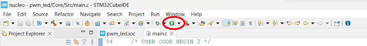
Next, click on the "Run and Debug" icon in the toolbar menu of the IDE (Refer to image below ). This will initiate the build process for your project. The IDE will compile the code. Once the build process is successful, the IDE will start flashing the compiled project to the STM32-F103RB Nucleo Board.
Output
Upon successfully running the project, you will observe the LED connected to PA8 on the STM32-F103RB Nucleo Board being controlled with varying brightness levels. The implemented PWM signals generated by the board's timers will enable smooth fading transitions.
Conclusion
Through this guide, you have gained valuable insights into working with timers, configuring PWM generation, and controlling GPIO pins on the STM32-F103RB Nucleo Board. You have also learned how to integrate these concepts into your code and observe the desired results on the connected LED. Experiment with different duty cycles and try creating visually appealing projects like mood lighting, and dynamic visual feedback systems.