Interfacing Buzzer with DE0 Nano FPGA
Introduction
Problem statement
Using a buzzer with FPGA DE0 Nano.
Requirements
- FPGA DE0 Nano
- Buzzer
- Jumper wires
Working
Code
Copy and paste the following code into buzzer.v or download it from here:
module buzzer (input  clk,output out);
  reg [31:0] counter;
  reg buzzer_signal;

  initial begin
    buzzer_signal = 1'b0;
    counter = 32'b0;
  end

  always @(posedge clk) begin
    if (counter < 25000000) counter <= counter + 1'b1;
    else begin
      buzzer_signal <= ~buzzer_signal;
      counter <= 32'b0;
    end
  end
  assign out = buzzer_signal;

endmodule
Processing-Pin Planner
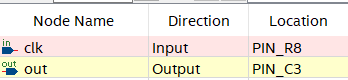
Open pin-planner and make the following assignment:
- clk assigned to PIN_R8.
- out assigned to PIN_C3.
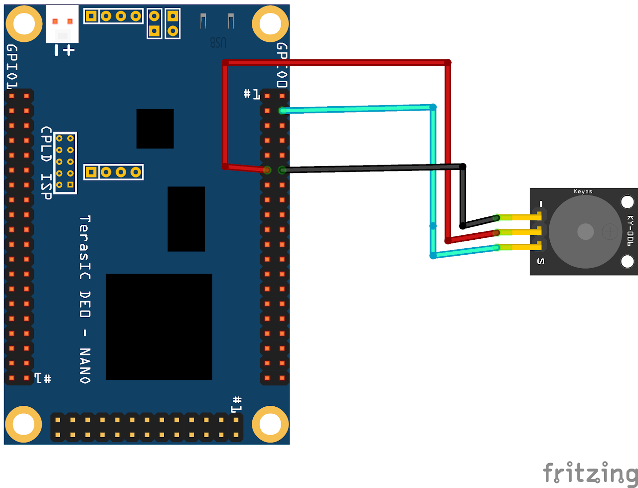
For Hardware Setup refer DE0 Nano Manual.
Upload the code on board and check the output.
Output
This code implements a basic buzzer functionality on an FPGA board. The buzzer produces a buzzing sound based on the clock signal and the counter value. The counter increments with each clock cycle, determining the timing of the buzzing effect. The buzzer signal is toggled based on the counter reaching a specific value, producing the desired buzzing sound. The output of the module is connected to the appropriate I/O pin on the FPGA board, allowing the buzzer to generate the buzzing sound according to the defined timing and toggle logic.
Conclusion
From this Verilog code for interfacing a buzzer in the DE0 Nano FPGA, we learned several key concepts. Firstly, we saw how to initialize and control signals using Verilog syntax, including the input (clk) and output (out) ports. We observed the use of a clock signal to synchronize the buzzing of the buzzer. The counter was used to determine the timing of the buzzing effect, allowing for a specific frequency. We also witnessed the usage of if-else conditions to handle the toggle action of the buzzer signal. Lastly, we gained insights into assigning the buzzer output value to the designated output port using the assign statement. Overall, this code demonstrated the fundamentals of interfacing a buzzer with an FPGA using Verilog, showcasing how to control the buzzing behavior based on the clock signal.