Interfacing Colour Sensor with DE0 Nano FPGA
Introduction:
The TCS3200 Color Sensor module has 8 pins; those are VCC, OUT, S3, S2, S1, S0, OUT, 0E, and GND. All the pins of this sensor module are digital, except VCC and Ground.
- VCC is the power supply pin of the color sensor that can be connected to 5V or 3.3V of the supply.
- S0 and S1: The S0 and S1 pins can be used to select the Output Frequency Scaling Percentage of the sensor. By configuring these pins it can be set to 2%, 20%, or 100% scaling.
- S2 and S3: The S2 & S3 pins can be used to select the color array of the sensor. By selecting the right color array one after the other, this sensor identifies a color.
- OE: This is the Output Enable or Disable pin of the color sensor module. This pin is pulled down on the module board to disable the sensor by giving a high pulse to this pin.
- OUT: This is the output pin of the sensor, when a particular color is detected by the sensor, the output pulse frequency on this pin changes, by detecting this change in pulse width we can determine the color.
- Ground is the ground pin of the Color Sensor module.
Problem Statement
Interfacing TCS3200 Colour Sensor with FPGA board. When the Colour Sensor senses Red, Green, and Blue colours the respective Red, Green, and Blue LEDS should glow.
Requirements
- De0 Nano FPGA board
- TCS3200 Colour Sensor
- Jumper wires
- RGB LED
- Breadboard
- Resistors
Working
The color sensor uses a very basic principle of light to identify the color. You see white is made up of three primary colors which are Red, Green, and Blue and each has different wavelengths. When light falls on a surface, depending on the material properties, it gets absorbed or reflected. That reflected light gets picked up by our eye and as a result, we can see colors.
Now let's look at how the TCS3200 color sensor works, we have the color sensor and we are giving high and low signals to the S0 and S1 pins of the sensor module which sets the sensor to 20% frequency scaling. That means the sensor will operate at a 200 KHz frequency. In this mode, the duty cycle of the sensor will remain at 50% but the output frequency of the sensor will change according to the color value. The S2 and S3 pins are used to select the array of photodiodes, for each color that is visible to the sensor we will set the array to red green and blue filter one by one. If the color detected by the sensor matches the selected array of the sensor, the output frequency of the sensor will increase and for any other situations the output frequency mostly stays the same or you can see a minute variation in the output frequency.
For more details refer to https://circuitdigest.com/microcontroller-projects/interfacing-color-sensor-with-arduino
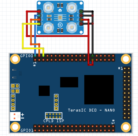
Circuit Diagram
- Connect Vcc and S1 to 3.3v pin
- Connect OE, S0, and Gnd to ground pin
- Connect Out pin to GPIO_00
- Connect the S2 pin to GPIO_01
- Connect the S3 pin to GPIO_03
Code
Copy and paste the following code into ColorSensor.v or download it from here:
// Main Module
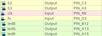
module ColourSensor(input clk,input fo,output S2, output S3,output reg ledR, output reg ledB, output reg ledG);
wire [31:0] R,G,B;
colour_sensor clrsense(clk,fo,R,B,G,S2,S3); //calling submodule
always @(posedge clk)begin
if((B>50)&(B<160)&(R>300)&(R<400)&(G>70)&(G<120)) begin
ledR = 1'b1;
ledG = 1'b0;
ledB = 1'b0;
end
else if ((B>150)&(B<200)&(R>200)&(R<250)&(G>300)&(G<350)) begin
ledG = 1'b1;
ledB = 1'b0;
ledB = 1'b0;
end
else if((B>350)&(B<440)&(R>60)&(R<130)&(G>90)&(G<190)) begin
ledR = 1'b0; bn bhm,
ledG = 1'b0;
ledB = 1'b1;
end
else begin
ledB=0;
ledG=0;
ledR=0;
end
end
endmodule
//submodule
module colour_sensor(clk,fo, Ri,Bi,Gi,S2,S3);
input clk,fo;
output [31:0]Ri,Bi,Gi;
reg [31:0] arr [2:0];
output reg S2,S3;
reg c;
reg [1:0] Sel;
integer count=0,tc,Clk_Count;
//tc: stors temporary values of count do that count does not keep changing
//Clk_count to count for 5Mhz/4 cycles and change filter
initial begin
tc=0;c=0;
end
always @(posedge clk)begin
case(Sel)
2'b00:begin S2 = 0; S3=0; end
2'b01: begin S2=0; S3 = 1; end
2'b10: begin S2 = 1; S3 = 1; end
endcase
if(Clk_Count==50000000/4)//using 50Mhz clk and changing filter type every 5Mhz/4 counts
begin
Clk_Count=0;
arr[Sel]=count;
Sel=Sel+1;
end
else
Clk_Count= Clk_Count+1;
if(Sel>2'b10)
Sel=2'b00;
if(fo)
begin
c=1;
tc= tc+1;
end
else begin
if(c==1)begin
count=tc;
c=0;
end
tc=0;
end
end
assign Ri = 50000000/(2*arr[0]); //calculates Red value after counting its frequency
assign Bi = 50000000/(2*arr[1]); //calculates Blue value after counting its frequency
assign Gi = 50000000/(2*arr[2]); //calculates Green value after counting its frequency
endmoduleOutput
- When a blue color paper or an object's color lies in the frequency range(mentioned in the code) of blue is taken near(2cm) the color sensor, the LED6 on FPGA Board glows.
- When a red color paper or an object's color lies in the frequency range(mentioned in the code) of red is taken near(2cm) the color sensor, the LED7 on board glows.
- When a green color paper or an object's color lies in the frequency range(mentioned in the code) of green is taken near(2cm) the color sensor, the LED5 on board glows.
- If the frequency of the object doesn't lie in any of the frequency ranges the LEDs remains off.
Conclusion
By interfacing a color sensor with an FPGA, various applications can be implemented, including color sensing and analysis in robotics, automation, quality control, image processing, and computer vision. The FPGA's flexibility and processing power allow for the customization and optimization of color-related algorithms, ensuring accurate and efficient color detection and analysis.
Interfacing a color sensor with an FPGA provides a powerful solution for real-time color sensing and analysis. It enables precise color detection, allows for complex color-related computations, and facilitates integration into larger systems. The FPGA's programmability and high-speed processing make it an excellent platform for implementing advanced color-based functionalities in diverse applications.