Interfacing LDR (Light) Sensor with ESP32 using ESP-IDF
Introduction
In this guide, we will learn how to interface an LDR (Light Dependent Resistor) sensor with the ESP32 microcontroller. The LDR sensor is used to detect light intensity. We will use the ESP32's GPIO pins to connect the LDR sensor and control an LED based on the light intensity detected by the sensor. When the light intensity is low, the LED will turn on, indicating low light conditions.
Problem Statement
The objective of this project is to interface the LDR sensor with the ESP32 and control an LED based on the light intensity detected by the sensor.
Requirements
To successfully complete this project, you will need the following components:
- ESP32 development board
- LDR sensor
- LED
- Resistor (220/330 ohms)
- Jumper wires
- Breadboard
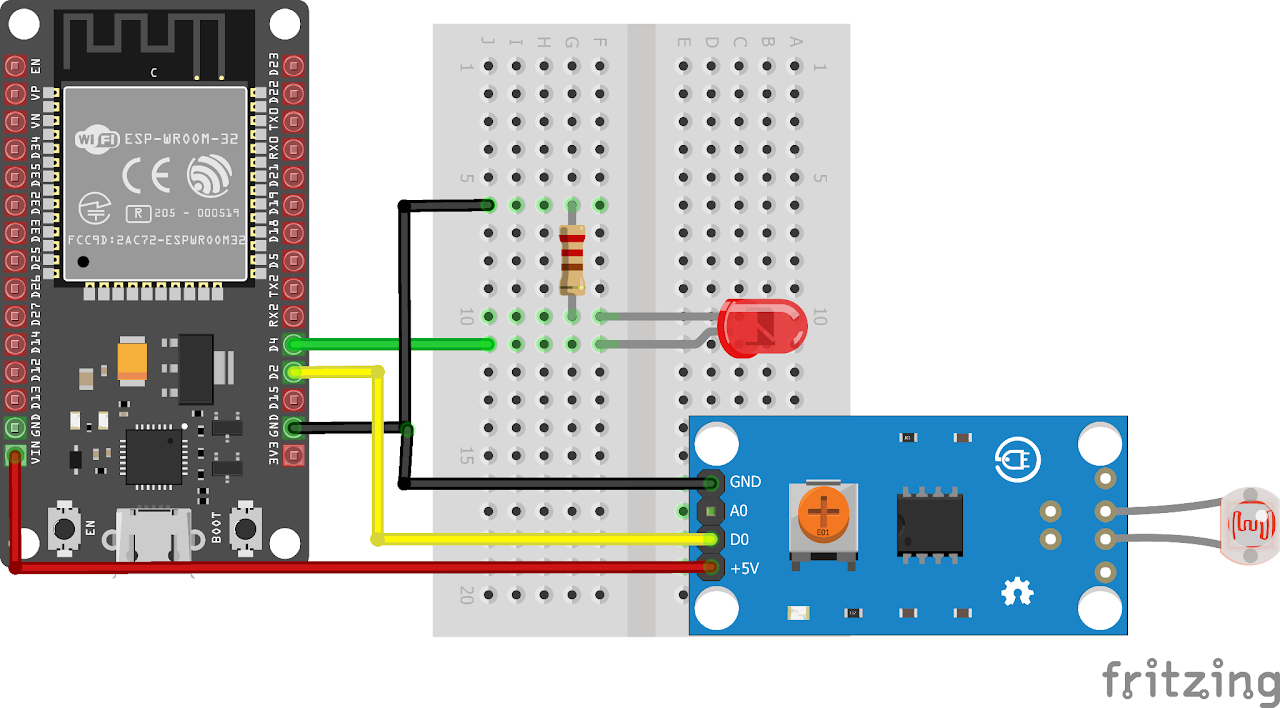
Circuit Diagram
Follow the circuit diagram below to connect the LED and LDR to the ESP32 development board:
Code:
Now let's understand and write the C code to detect the presence of the object. Follow the steps below:
Open VS Code and create a new sample project with the name light_sensor (Follow previous guides to see how to do it).
Now navigate to the "Main" folder of the project and then open the Main.c file.
Copy and paste the following code into Main.c or download the code from here:
(LDR Sensor used in this case was active low, please change the code according to your components)
#include <stdio.h>
#include "driver/gpio.h"
#include "freertos/FreeRTOS.h"
#include "freertos/task.h"

#define LDR_PIN GPIO_NUM_2
#define LED_PIN GPIO_NUM_4

void app_main(void)
{
    // Initialize GPIO5 as input for LDR sensor
    gpio_set_direction(LDR_PIN, GPIO_MODE_INPUT);

    // Initialize GPIO4 as output for LED
    gpio_set_direction(LED_PIN, GPIO_MODE_OUTPUT);

    while (1)
    {
        // If light is detected, turn off the LED
        if (!gpio_get_level(LDR_PIN))
        {
            gpio_set_level(LED_PIN, 0);
            printf("Light detected, switching off the LED.\n");
        }
        else
        {
            gpio_set_level(LED_PIN, 1);
        }
        vTaskDelay(10); // 10ms delay
    }
}- Now at the bottom navbar of VS Code select the port, flash method and click on the Build, flash and monitor icon.
Note: During the flashing process of your board, you may encounter an error. If this happens, there's no need to worry. Simply flash the board again and when you see the message "connecting..........." appear, press and hold the boot button on your board for 1 or 2 seconds. Keep holding it until the dots on the screen start disappearing or the further flashing process begins. This action will help resolve any issues and ensure a successful flashing of your board.
Output
After uploading the code to the ESP32, the program will continuously monitor the light intensity detected by the LDR sensor. If the light intensity is low (indicating low light conditions), the LED will turn on. Conversely, if the light intensity is high (indicating sufficient light conditions), the LED will turn off. The program will display a message on the console whenever the light is detected or when the LED is switched off.
Conclusion
By following this guide, you have successfully interfaced the LDR sensor with the ESP32 microcontroller. You can now control an LED based on the light intensity detected by the sensor. This project can be expanded further by incorporating additional features, such as adjusting the LED brightness based on the light intensity or integrating it into a home automation system.