Controlling Led brightness on ESP32 using ESP-IDF
Introduction
In this guide, we will demonstrate how to control the brightness of an LED using Pulse Width Modulation (PWM) with an ESP32 microcontroller using the ESP-IDF VS Code extension. We will write C code to gradually vary the LED's brightness using PWM signals generated by the ESP32. This project can be useful in various applications such as mood lighting, visual feedback systems, and ambient lighting control.
Problem Statement
The objective is to control the brightness of an LED using PWM signals generated by the ESP32 microcontroller.
Requirements
To successfully complete this project, you will need the following components:
- ESP32 development board
- LED
- Resistor (220-330 ohms)
- Jumper wires
- Breadboard
Circuit Diagram
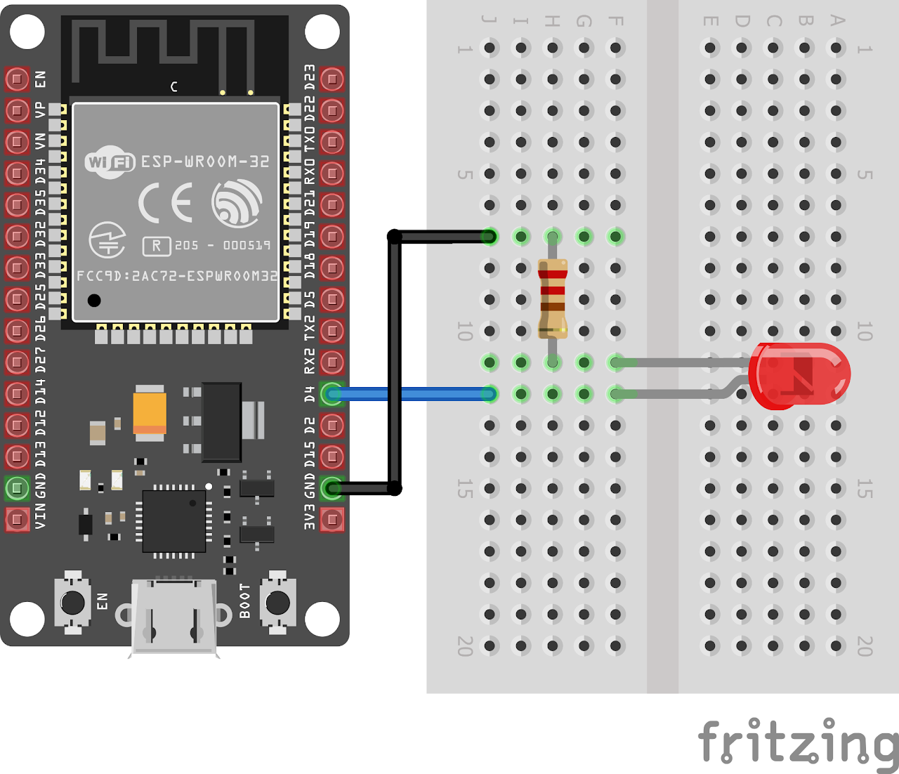
Follow the circuit diagram below to connect the LED to the ESP32 development board:
- Connect the anode (long leg) of the LED to GPIO pin 4 (LED_PIN) of the ESP32.
- Connect the cathode (short leg) of the LED to a resistor (220 ohms).
- Now connect the other end of the resistor to the ground (GND) pin of the ESP32.
Code:
Now let's understand and write the C code to control the brightness of LED. Follow the steps below:
- Open VS Code and create a new sample project (Follow previous guides to see how to do it).
- Now navigate to the "Main" folder and then open the Main.c file.
- Now copy and paste the following code into Main.c: (The source code is accessible here)
#include <stdio.h>
#include <freertos/FreeRTOS.h>
#include <freertos/task.h>
#include <driver/ledc.h>
// Define the GPIO pin connected to the LED
#define LED_PIN GPIO_NUM_4

// PWM configuration
#define PWM_CHANNEL LEDC_CHANNEL_0       // Use channel 0
#define PWM_TIMER LEDC_TIMER_0           // Use timer 0
#define PWM_FREQ_HZ 1000                 // Frequency of PWM signal 1kHz
#define PWM_RESOLUTION LEDC_TIMER_10_BIT // 10-bit resolution

void app_main()
{
    // Configure the LED pin as output
    gpio_set_direction(LED_PIN, GPIO_MODE_OUTPUT);
    // Create a task to control the PWM
    // Configure PWM settings
    ledc_timer_config_t pwmTimerConfig = {
        .duty_resolution = PWM_RESOLUTION,
        .freq_hz = PWM_FREQ_HZ,
        .speed_mode = LEDC_HIGH_SPEED_MODE,
        .timer_num = PWM_TIMER};
    ledc_timer_config(&pwmTimerConfig);

    // Configure PWM channel
    ledc_channel_config_t pwmChannelConfig = {
        .channel = PWM_CHANNEL,
        .duty = 0,
        .gpio_num = LED_PIN,
        .speed_mode = LEDC_HIGH_SPEED_MODE,
        .hpoint = 0,
        .timer_sel = PWM_TIMER};
    ledc_channel_config(&pwmChannelConfig);
    // Start the PWM
    ledc_fade_func_install(0);
    ledc_set_duty(LEDC_HIGH_SPEED_MODE, PWM_CHANNEL, 0);
    ledc_update_duty(LEDC_HIGH_SPEED_MODE, PWM_CHANNEL);

    // Contol the PWM duty cycle
    while (1)
    {
        // Increase the duty cycle from 0% to 100%
        for (int duty = 0; duty <= (1 << PWM_RESOLUTION) - 1; duty++)
        {
            ledc_set_duty(LEDC_HIGH_SPEED_MODE, PWM_CHANNEL, duty);
            ledc_update_duty(LEDC_HIGH_SPEED_MODE, PWM_CHANNEL);
            vTaskDelay(pdMS_TO_TICKS(10));
        }

        // Decrease the duty cycle from 100% to 0%
        for (int duty = (1 << PWM_RESOLUTION) - 1; duty >= 0; duty--)
        {
            ledc_set_duty(LEDC_HIGH_SPEED_MODE, PWM_CHANNEL, duty);
            ledc_update_duty(LEDC_HIGH_SPEED_MODE, PWM_CHANNEL);
            vTaskDelay(pdMS_TO_TICKS(10));
        }
    }
}- Now at the bottom navbar of VS Code select the port, flash method and click on the Build, flash and monitor icon.
Note: During the flashing process of your board, you may encounter an error. If this happens, there's no need to worry. Simply flash the board again and when you see the message "connecting..........." appear, press and hold the boot button on your board for 1 or 2 seconds. Keep holding it until the dots on the screen start disappearing or the further flashing process begins. This action will help resolve any issues and ensure a successful flashing of your board.
Output
After flashing the code to the ESP32, the LED will gradually increase and decrease its brightness in a smooth loop, creating a fading effect.
Conclusion
By following this guide, you have successfully controlled the brightness of an LED using PWM signals generated by an ESP32 microcontroller. The ESP-IDF and VS Code extension were used to develop and flash the code to the ESP32. This project can be extended to control multiple LEDs, create dynamic lighting effects, or integrate with other sensors and actuators for more advanced applications.