External Switch Interrupt with ESP32
Introduction
This guide will demonstrate how to interface an external switch with an ESP32 microcontroller and utilize interrupts to detect button presses. Upon a button press, an LED connected to the ESP32 will turn off for a specific duration. This project showcases the capabilities of GPIO interrupts and their application in real-time event handling
Problem Statement
The objective of this project is to work with interrupts on ESP32 microcontroller. We will use a push button and LED to demonstrate the interrupts.
Requirements
To successfully complete this project, you will need the following components:
- ESP32 development board
- Push Button
- LED
- Resistor (220 ohms)
- Breadboard and jumper wires
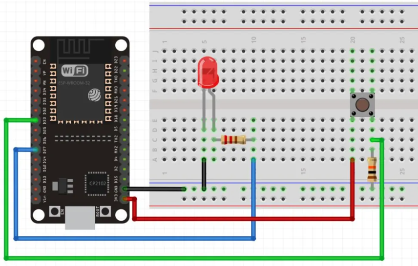
Circuit Diagram
Follow the circuit diagram below to connect the push button and led to the ESP32 development board:
- Connect one terminal of the external switch to the ESP32's GPIO 2 (D2) and the other terminal to ground.
- Connect the LED's anode (longer leg) to the ESP32's GPIO 4 pin (D4) and the cathode (shorter leg) to a resistor connected to ground.
Code:
Now let's understand and write the C code to check for interrupt. Follow the steps below:
Open VS Code and create a new sample project with the name switch_interrupt (Follow previous guides to see how to do it).
Now navigate to the "Main" folder of the project and then open the Main.c file.
Copy and paste the following code into Main.c or download the code from here:
#include <stdio.h>
#include "freertos/FreeRTOS.h"
#include "freertos/task.h"
#include "freertos/queue.h"
#include "driver/gpio.h"
#include <stdio.h>
#include "freertos/FreeRTOS.h"
#include "freertos/task.h"
#include "freertos/queue.h"
#include "driver/gpio.h"
/*
********************************************************************************
ESP32 GPIO Interrupts
If button pressed, turn off LED for 500ms
********************************************************************************/

#define BUTTON_PIN GPIO_NUM_33
#define LED_PIN GPIO_NUM_27
#define ESP_INTR_FLAG_DEFAULT 0

static QueueHandle_t gpio_evt_queue = NULL;

static void IRAM_ATTR button_isr_handler(void *arg)
{
    uint32_t gpio_num = (uint32_t)arg;
    xQueueSendFromISR(gpio_evt_queue, &gpio_num, NULL); // Send the ISR's gpio_num argument to the queue
}

static void button_task(void *arg)
{
    while (true)
    {
        uint32_t gpio_num;
        // printf("Waiting for button press interrupt\n");
        if (xQueueReceive(gpio_evt_queue, &gpio_num, portMAX_DELAY))
        {
            printf("Button pressed! Interrupt occurred on GPIO %ld\n", gpio_num);
            gpio_set_level(LED_PIN, 0); // Turn off the LED
        }
    }
}

void app_main()
{
    gpio_config_t io_conf;

    // Configure the button pin as input with pull-up resistor
    io_conf.intr_type = GPIO_INTR_NEGEDGE;
    io_conf.mode = GPIO_MODE_INPUT;
    io_conf.pin_bit_mask = (1ULL << BUTTON_PIN);
    io_conf.pull_up_en = GPIO_PULLUP_ENABLE;
    gpio_config(&io_conf);

    // Configure the LED pin as output
    io_conf.mode = GPIO_MODE_OUTPUT;
    io_conf.pin_bit_mask = (1ULL << LED_PIN);
    gpio_config(&io_conf);

    // Create a queue to handle button events
    gpio_evt_queue = xQueueCreate(10, sizeof(uint32_t));
    if (gpio_evt_queue == NULL)
    {
        printf("Failed to create GPIO event queue\n");
        return;
    }

    // Configure and install the ISR (Interrupt Service Routine)
    gpio_install_isr_service(ESP_INTR_FLAG_DEFAULT);
    gpio_isr_handler_add(BUTTON_PIN, button_isr_handler, (void *)BUTTON_PIN);

    // Create a task to handle button events
    xTaskCreate(button_task, "button_task", 2048, NULL, 5, NULL); // Higher priority than the LED task

    while (true)
    {
        vTaskDelay(500 / portTICK_PERIOD_MS);
        gpio_set_level(LED_PIN, 1); // Turn on the LED
    }
}- Now at the bottom navbar of VS Code select the port, flash method and click on the Build, flash and monitor icon.
Note: During the flashing process of your board, you may encounter an error. If this happens, there's no need to worry. Simply flash the board again and when you see the message "connecting..........." appear, press and hold the boot button on your board for 1 or 2 seconds. Keep holding it until the dots on the screen start disappearing or the further flashing process begins. This action will help resolve any issues and ensure a successful flashing of your board.
Output
Upon successful flashing and proper connections, the LED initially turns on. When the external switch/button is pressed, the LED turns off.
Repeat the process each time the button is pressed. You will also see an output on serial monitor each time interrupt occurs.
Conclusion
By following this guide, you have successfully interfaced an external switch with an ESP32 using interrupts. You have learned how to handle button press events using GPIO interrupts and perform specific actions, such as turning off an LED. This knowledge can be applied to various projects that require real-time event detection and response using interrupts. Feel free to explore additional functionalities and expand on this project to suit your specific requirements.