Interfacing DC Fan with ESP32
Introduction
In this guide, we will learn how to interface a 5V DC fan with an ESP32 microcontroller and control its speed using Pulse Width Modulation (PWM). PWM allows us to adjust the average power delivered to the fan, thus controlling its speed.
Problem Statement
The objective of this project is to interface a 5V DC fan with ESP32 microcontroller using PWM for speed control. The system should allow the ESP32 to adjust the fan speed based on the desired PWM duty cycle.
Requirements
To successfully complete this project, you will need the following components:
- ESP32 development board
- Fan (DC fan)
- L298N Motor driver module
- Power supply for the motor driver (5V)
- Jumper wires
Working
Pulse Width Modulation (PWM) is a technique used to control the average voltage or power supplied to a device by rapidly switching it ON and OFF. It works by varying the width or duration of the ON state (duty cycle) while keeping the frequency constant.
In the case of fan speed control, PWM is used to adjust the voltage supplied to the fan motor by adjusting the duty cycle of the PWM signal. By increasing or decreasing the duty cycle, we can effectively control the average power supplied to the fan motor, thus controlling its speed.
Why Motor Driver is Required and How it Works:
The goal is to control the speed of a fan connected to a Raspberry Pi using PWM. However, as the Raspberry Pi's GPIO pins cannot provide the required voltage directly, we will use a motor driver module to drive the fan motor effectively. The motor driver module, such as the L298N, is used to provide the necessary power and control signals to drive the fan motor effectively.
The L298N, is a popular dual H-bridge module capable of driving DC motors. It has input pins (in3_pin and in4_pin) to control the direction of rotation of the motor, and an enable pin (enable_pin) to control the motor's speed. (In this guide, we will only focus on speed and not direction)
By adjusting the PWM duty cycle, we vary the average power supplied to the fan motor. The motor driver module, connected to the enable pin, takes the PWM signal from the Raspberry Pi and adjusts the voltage supplied to the fan motor accordingly, thus controlling its speed.
Since we will be controlling speed only, we will connect the in4 pin of the motor driver to the pin next to enB (enable_B) pin. This pin is a 5v pin which would make sure that in4 is high and in3 would be low as it is not connected to anything. So in this case, direction will be forward.
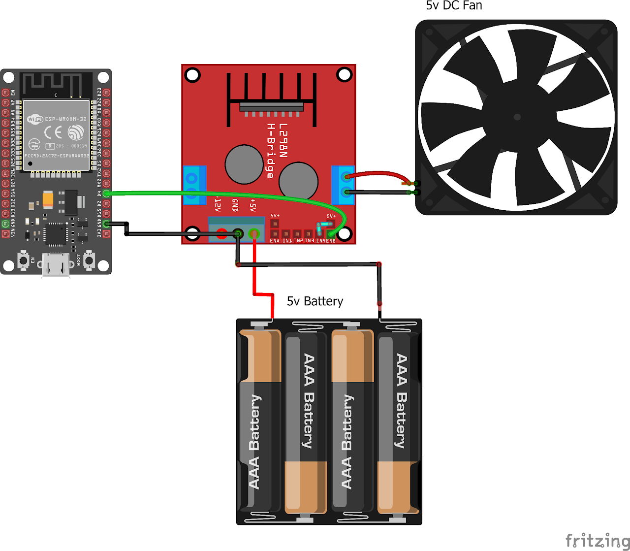
Circuit Diagram
Follow the circuit diagram below to connect the Fan and motor driver with the ESP32 development board:
Code:
Now let's understand and write the C code to detect the presence of the object. Follow the steps below:
- Open VS Code and create a new sample project with the name light_sensor (Follow previous guides to see how to do it).
- Now navigate to the "Main" folder of the project and then open the Main.c file.
- Copy and paste the following code into Main.c or download the code from here:
#include <stdio.h>
#include <freertos/FreeRTOS.h>
#include <freertos/task.h>
#include <driver/ledc.h>

// Define the GPIO pin connected to the DC FAN
#define FAN_PIN GPIO_NUM_4

// PWM configuration
#define PWM_CHANNEL LEDC_CHANNEL_0       // Use channel 0
#define PWM_TIMER LEDC_TIMER_0           // Use timer 0
#define PWM_FREQ_HZ 1000                 // Frequency of PWM signal 1kHz
#define PWM_RESOLUTION LEDC_TIMER_10_BIT // 10-bit resolution

void app_main()
{
    // Configure the FAN pin as output
    gpio_set_direction(FAN_PIN, GPIO_MODE_OUTPUT);

    // Create a task to control the PWM
    // Configure PWM settings
    ledc_timer_config_t pwmTimerConfig = {
        .duty_resolution = PWM_RESOLUTION,
        .freq_hz = PWM_FREQ_HZ,
        .speed_mode = LEDC_HIGH_SPEED_MODE,
        .timer_num = PWM_TIMER};
    ledc_timer_config(&pwmTimerConfig);

    // Configure PWM channel
    ledc_channel_config_t pwmChannelConfig = {
        .channel = PWM_CHANNEL,
        .duty = 0,
        .gpio_num = FAN_PIN,
        .speed_mode = LEDC_HIGH_SPEED_MODE,
        .hpoint = 0,
        .timer_sel = PWM_TIMER};
    ledc_channel_config(&pwmChannelConfig);
    // Start the PWM
    ledc_fade_func_install(0);
    ledc_set_duty(LEDC_HIGH_SPEED_MODE, PWM_CHANNEL, 0);
    ledc_update_duty(LEDC_HIGH_SPEED_MODE, PWM_CHANNEL);

    // Control the PWM duty cycle
    while (1)
    {
        // Increase the duty cycle from 0% to 100%
        for (int duty = 0; duty <= (1 << PWM_RESOLUTION) - 1; duty++)
        {
            ledc_set_duty(LEDC_HIGH_SPEED_MODE, PWM_CHANNEL, duty);
            ledc_update_duty(LEDC_HIGH_SPEED_MODE, PWM_CHANNEL);
            vTaskDelay(pdMS_TO_TICKS(10));
        }

        // Decrease the duty cycle from 100% to 0%
        for (int duty = (1 << PWM_RESOLUTION) - 1; duty >= 0; duty--)
        {
            ledc_set_duty(LEDC_HIGH_SPEED_MODE, PWM_CHANNEL, duty);
            ledc_update_duty(LEDC_HIGH_SPEED_MODE, PWM_CHANNEL);
            vTaskDelay(pdMS_TO_TICKS(10));
        }
    }
}- Now at the bottom navbar of VS Code select the port, flash method and click on the Build, flash and monitor icon.
Note: During the flashing process of your board, you may encounter an error. If this happens, there's no need to worry. Simply flash the board again and when you see the message "connecting..........." appear, press and hold the boot button on your board for 1 or 2 seconds. Keep holding it until the dots on the screen start disappearing or the further flashing process begins. This action will help resolve any issues and ensure a successful flashing of your board.
Output
After uploading the code to the ESP32, the fan should start spinning at the desired speed according to the PWM settings. Monitor the fan speed and adjust the PWM settings as needed.
Conclusion
By following this guide, you have successfully interfaced a 5V DC fan with an ESP32 microcontroller using PWM speed control. You can now adjust the fan speed according to your requirements by modifying the PWM duty cycle in the code. This setup can be used in various applications such as cooling systems, temperature control, and ventilation projects.