Interfacing DC Motor with DE0 Nano FPGA
Introduction:
A DC motor is an electrical motor that converts direct current electrical energy into mechanical energy. The most common types rely on the forces produced by induced magnetic fields due to flowing current in the coil. Nearly all types of DC motors have some internal mechanism, either electromechanical or electronic, to periodically change the direction of current in a part of the motor.
Problem Statement
To effectively control DC motors using DE0 Nano FPGA.
Requirements
- DE0 Nano FPGA
- Breadboard
- DC Motor
- Motor Driver(L298)
- Jumper wires
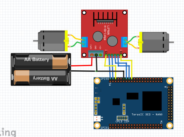
Circuit Diagram
- Connect IN1 and IN2 of motor driver to GPIO_01 and GPIO_03 respectively
- Connect IN3 and IN3 of motor driver to GPIO_09 and GPIO_11 respectively
- Connect the ENA and ENB of the motor driver to GPIO_00 and GPIO_13 respectively
- Connect the 12v power supply to the motor driver and connect the ground of FPGA and the motor driver
- Connect dc motors to the output of the motor driver
Code
Copy and paste the following code into dcmotor.v or download it from here:
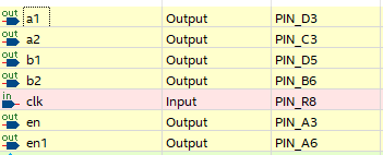
module dcmotor(clk,a1,a2,b1,b2,en,en1);
input clk;
output reg a1,a2,b1,b2;
output reg en;
output reg en1;
reg pwm;
reg pwm1;
reg [9:0] count;
reg [9:0] count1;
reg n=0;     //if n=0, it enters into case0

             //if n=1, it enters into case1


always @(posedge clk)
begin

count<= count+1 ;          //incrementing count for generating PWM
if(count== 10'b1111111111)
count<=0;                  //count becomes zero when it reaches its maximum value

pwm<= (count<10'b1111111111)?1:0;  //PWM generation using ternary operator


count1<= count1+1 ;            //incrementing count for generating PWM
if(count1== 10'b1111111111)
count1<=0;                     //count1 becomes zero when it reaches its maximum value

pwm1<= (count1<10'b0000001111)?1:0;  //PWM generation using ternary operator

case (n)

0:     //case0 makes both the motor rotate in same direction
begin

en<=pwm;
a1<=1;
a2<=0;

en1<=pwm1;
b1<=1;
b2<=0;

end

1:    //case1 makes both the motor rotate in different direction
begin

en<=pwm;
a1<=1;
a2<=0;

en1<=pwm1;
b1<=0;
b2<=1;

end
endcase

end
endmodule
Output
If n=0, one of the motors rotates at a higher speed than the other. Both the motor rotates in the same direction which makes the robot moves in the forward direction.
If the value of n is changed to 1, then both motors rotate in a different direction with different speeds which makes the robot move in the backward direction.
The speed of the motors can be changed as required by changing the bits of the pwm and pwm1 ternary operator.
Conclusion
By interfacing a DC motor with an FPGA, precise and flexible motor control can be achieved in various applications, including robotics, automation, motorized systems, and industrial control. The FPGA's programmability allows for the customization of motor control algorithms, integration with other system components, and the implementation of advanced control features.
Interfacing a DC motor with an FPGA provides a powerful solution for controlling motor speed, direction, and torque with high accuracy and flexibility. The FPGA's programmable logic and high-speed processing enable real-time motor control, making it suitable for applications that require precise motor control and dynamic response.