Interfacing the LCD with the STM32-F103RB Nucleo Board
Introduction
Problem Statement
Requirements
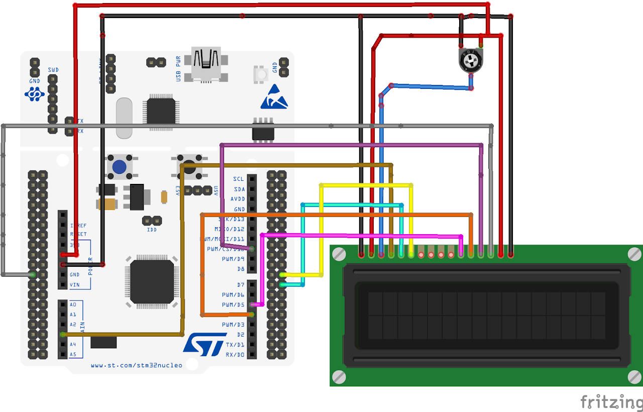
Follow the circuit diagram below to properly connect the LCD module to the STM32-F103RB :
- Nucleo-F103RB board
- 16 x 2 LCD
- Potentiometer (10K Ohms)
- Jumper wires
- Breadboard
Circuit Diagram
Follow the circuit diagram below to connect the LCD to the Nucleo board:
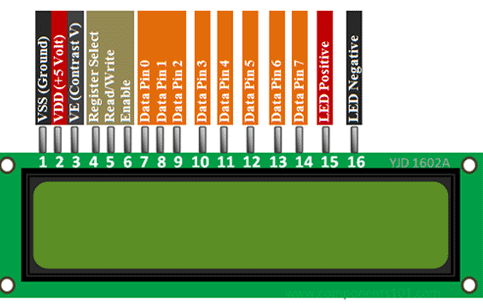
- Connect the RS (Register Select) pin of the LCD to PB0 Pin of the board.
- Connect the RW (Read/Write) pin of the LCD to PB1 Pin of the board.
- Connect the EN (Enable) pin of the LCD to PB2 Pin of the board.
- Connect the D4 pin of the LCD to PB4 Pin of the board.
- The D5 pin of the LCD to PB5 Pin of the board.
- Connect the D6 pin of the LCD to PB6 Pin of the board.
- And the D7 pin of the LCD to PB7 Pin of the board.
16x2 LCD Module Pinout
Project Configuration
Follow these steps to configure the .IOC file and set up GPIOs and Clock :
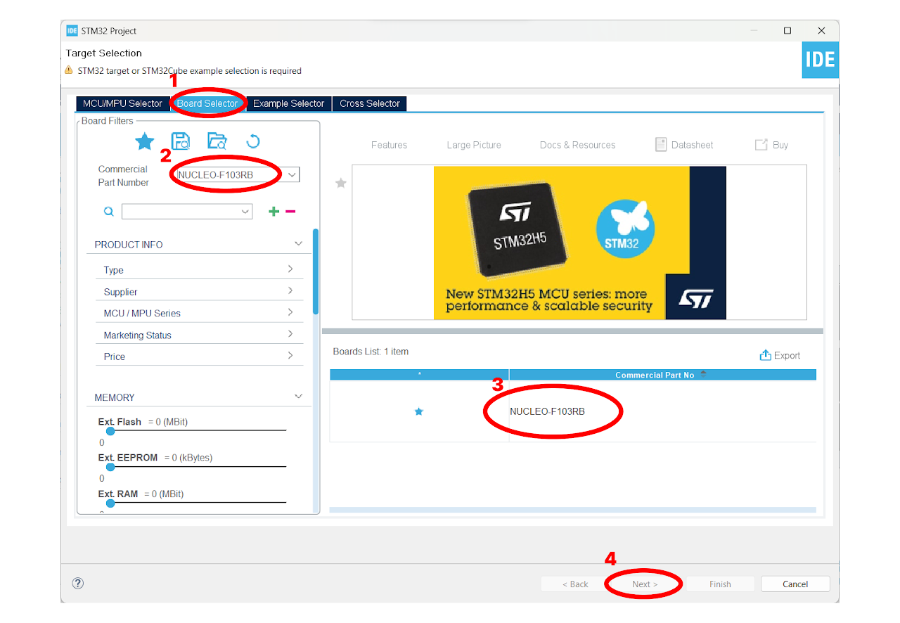
Open the STM32 Cube IDE and start by creating a new STM32 project. Click on the board selector tab in the target selection window.
Enter "NUCLEO-F103RB" as the commercial part number and click on "Next" after selecting the board.
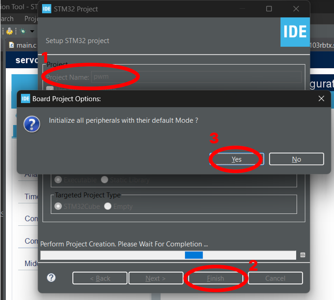
- Enter the Project Name "lcd" and click on "Finish". After that, click on "Yes" to initialize all the peripherals in default mode.
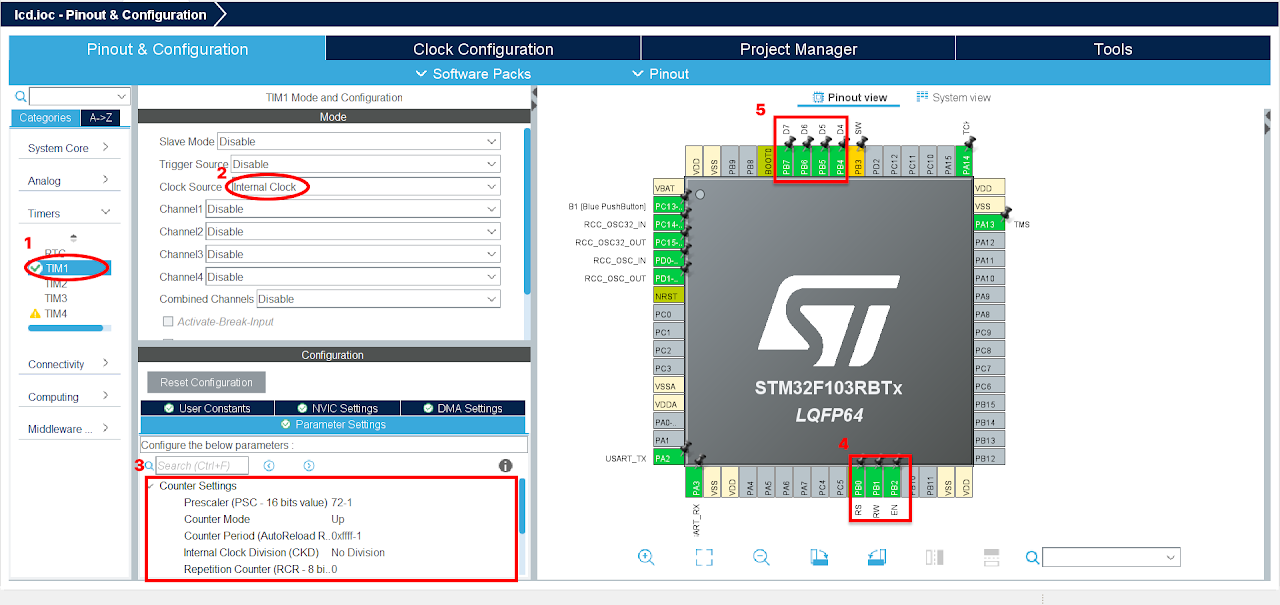
Pinout & Configuration: In the Pinout & Configuration menu, select "TIM1" from the Timers section. This will configure Timer 1 for generating delay.
Clock Source: Choose "Internal Clock" as the Clock Source to utilize the internal clock of the STM32-F103RB Nucleo Board.
Timer Configuration: In the Configuration part of the Timers section, set the prescaler value as "72-1". The prescaler determines the frequency of the timer clock. Here, we divide the timer clock frequency by 72.
Next, specify the Counter Period as "0xffff-1". The counter period defines the overall period of the timer, this will be useful in writing a delay function in LCD.
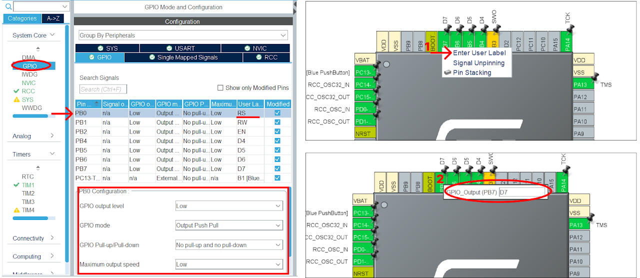
To configure the GPIO pins for output, click on the GPIO pin in the Pinout & Configuration tab. Select the "GPIO_Output" option from the available options. To add a user label, right-click on the GPIO pin and select the "User Label" option and enter the desired name for the label.
Configure the GPIO pins highlighted in the 4th and 5th boxes in the image above as output, and rename them as shown below. These labels are predefined in the provided library
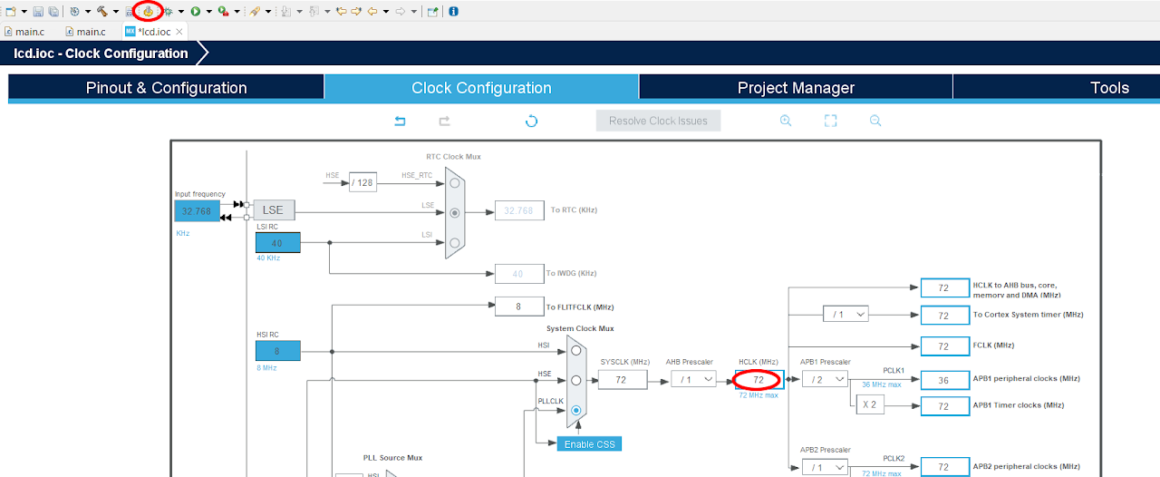
After finishing the Pinout Configuration, go to the Clock Configuration menu. In the HCLK field, enter "72 MHz" as the desired frequency for the HCLK (system clock). The Integrated Development Environment (IDE) will automatically search for the necessary clock sources and prescalers based on this configuration.
Next, locate the gear-like icon on the toolbar and click on it. This will add the configuration settings we did in the GUI to the code.
Code
Now, let's proceed to understand and write the C code to interface the LCD. Follow the steps below:
Open the main.c file, which is automatically opened by the Device Configuration Tool.
Include the necessary header file for the LCD module. Include the source file for the LCD module.
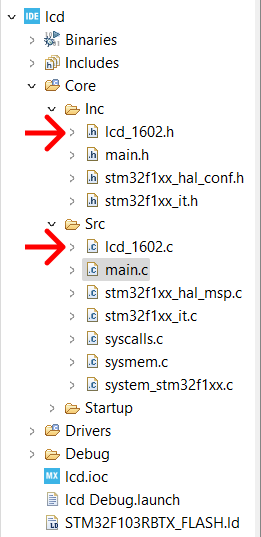
Download the "lcd_1602.c" and "lcd_1602.h" file from this link and add it to your project. Ensure that the project structure includes the added header and source files. And your project structure should look as below:
- After adding the header and source file, copy the below code into your main.c file to replace the main function only .
Note: You can download the full project code from the provided link.
#include "lcd_1602.h"

int main(void)
{
    /* MCU Configuration--------------------------------------------------------*/
    /* Reset of all peripherals, Initializes the Flash interface and the Systick. */
    HAL_Init();
    /* Configure the system clock */
    SystemClock_Config();
    /* Initialize all configured peripherals */
    MX_GPIO_Init();
    MX_USART2_UART_Init();
    MX_TIM1_Init();
    /* USER CODE BEGIN 2 */
    HAL_TIM_Base_Start(&htim1);
    // Set cursor to 0,0
    lcd_init();
    lcd_put_cur(0, 0);
    // Print Hello World
    lcd_send_string("HELLO ");
    lcd_send_string("WORLD ");
    lcd_send_string("FROM");
    // Set cursor to second row
    lcd_put_cur(1, 0);
    lcd_send_string("LAB IN A BOX!");
    HAL_Delay(3000);
    /* USER CODE END 2 */

    while (1)
    {
        /* USER CODE END WHILE */
    }
    /* USER CODE BEGIN 3 */
}
After pasting the above code, ensure that you have connected your STM32-F103RB Nucleo Board to your PC/Laptop using a USB cable.
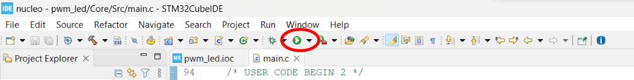
Next, click on the "Run and Debug" icon in the toolbar menu of the IDE (Refer to image below ). This will initiate the build process for your project. The IDE will compile the code. Once the build process is successful, the IDE will start flashing the compiled project to the STM32-F103RB Nucleo Board.
Output
Once the code is uploaded and running on the STM32-F103RB Nucleo Board, the LCD module will display the "HELLO WORLD FROM LAB IN A BOX!". Adjust the contrast by rotating the potentiometer.
Conclusion
By following this guide, you have successfully learned how to interface an LCD with the STM32-F103RB Nucleo Board. You have understood the hardware connections, library installation, and code implementation necessary for displaying information on the LCD. Now, you can utilize the LCD for visual outputs, menu navigation, and user interface in your STM32-based projects.