Interfacing Servo Motor with ESP32
Introduction
In this guide, we will learn how to interface a servo motor with the ESP32 microcontroller. A servo motor is a widely used device that allows precise control of angular position. We will use the ESP32's GPIO pins and the LEDC (LED Control) module to generate PWM (Pulse Width Modulation) signals required to control the servo motor's position.
Problem Statement
The objective of this project is to interface a servo motor with the ESP32 and control its position by generating appropriate PWM signals.
Requirements
To successfully complete this project, you will need the following components:
- ESP32 development board
- Servo motor
- Jumper wires
- Breadboard
Circuit Diagram
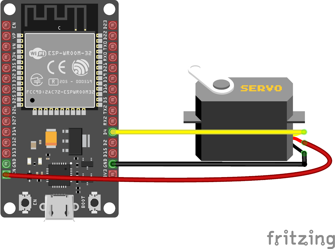
Follow the circuit diagram below to connect the Servo motor to the ESP32 development board:
- Connect the signal pin from servo to the GPIO 4 (D4) of the ESP32.
- Also connect the Power to the Vin of ESP32 and GND to the GND of the ESP32.
Code
Now let's understand and write the C code to control the servo motor. Follow the steps below:
Open VS Code and create a new sample project with the name servo_interface (Follow previous guides to see how to do it).
Now navigate to the "Main" folder of the project and then open the Main.c file.
Copy and paste the following code into Main.c or download the code from here:
#include <stdio.h>
#include <freertos/FreeRTOS.h>
#include <freertos/task.h>
#include <driver/ledc.h>

// Define the GPIO pin connected to the servo motor
#define SERVO_PIN GPIO_NUM_4

// PWM configuration
#define PWM_CHANNEL LEDC_CHANNEL_0       // Use channel 0
#define PWM_TIMER LEDC_TIMER_0           // Use timer 0
#define PWM_FREQ_HZ 50                   // Frequency of PWM signal 50Hz
#define PWM_RESOLUTION LEDC_TIMER_12_BIT // 12-bit resolution

// Servo configuration
#define SERVO_MIN_ANGLE 0   // Minimum angle for the servo (in degrees)
#define SERVO_MAX_ANGLE 180 // Maximum angle for the servo (in degrees)
#define SERVO_MIN_DUTY 50   // Minimum duty cycle for the servo (in microseconds)
#define SERVO_MAX_DUTY 2450 // Maximum duty cycle for the servo (in microseconds)

void servoTask(void *pvParameters)
{
    while (1)
    {
        for (int angle = SERVO_MIN_ANGLE; angle <= SERVO_MAX_ANGLE; angle++)
        {
            // Calculate duty cycle based on the angle
            int duty = (SERVO_MAX_DUTY - SERVO_MIN_DUTY) * angle / (SERVO_MAX_ANGLE - SERVO_MIN_ANGLE) + SERVO_MIN_DUTY;

            // Set the duty cycle for the servo
            ledc_set_duty(LEDC_HIGH_SPEED_MODE, PWM_CHANNEL, duty);
            ledc_update_duty(LEDC_HIGH_SPEED_MODE, PWM_CHANNEL);
            vTaskDelay(pdMS_TO_TICKS(10));
        }
        vTaskDelay(1000 / portTICK_PERIOD_MS);
        for (int angle = SERVO_MAX_ANGLE; angle >= SERVO_MIN_ANGLE; angle--)
        {
            // Calculate duty cycle based on the angle
            int duty = (SERVO_MAX_DUTY - SERVO_MIN_DUTY) * angle / (SERVO_MAX_ANGLE - SERVO_MIN_ANGLE) + SERVO_MIN_DUTY;
            // Set the duty cycle for the servo
            ledc_set_duty(LEDC_HIGH_SPEED_MODE, PWM_CHANNEL, duty);
            ledc_update_duty(LEDC_HIGH_SPEED_MODE, PWM_CHANNEL);
            vTaskDelay(pdMS_TO_TICKS(10));

        }
        vTaskDelay(1000 / portTICK_PERIOD_MS);
    }
}

void app_main()
{

    // Configure the servo pin as output
    gpio_set_direction(SERVO_PIN, GPIO_MODE_OUTPUT);
    // Configure PWM settings
    ledc_timer_config_t pwmTimerConfig = {
        .duty_resolution = PWM_RESOLUTION,
        .freq_hz = PWM_FREQ_HZ,
        .speed_mode = LEDC_HIGH_SPEED_MODE,
        .timer_num = PWM_TIMER};
    ledc_timer_config(&pwmTimerConfig);
    // Configure PWM channel
    ledc_channel_config_t pwmChannelConfig = {
        .channel = PWM_CHANNEL,
        .duty = 0,
        .gpio_num = SERVO_PIN,
        .speed_mode = LEDC_HIGH_SPEED_MODE,
        .hpoint = 0,
        .timer_sel = PWM_TIMER};
    ledc_channel_config(&pwmChannelConfig);

    // Start the PWM
    ledc_fade_func_install(0);
    ledc_set_duty(LEDC_HIGH_SPEED_MODE, PWM_CHANNEL, 0);
    ledc_update_duty(LEDC_HIGH_SPEED_MODE, PWM_CHANNEL);

    // Create a task to control the servo
    xTaskCreate(servoTask, "servo_task", 2048, NULL, 5, NULL);
}- Now at the bottom navbar of VS Code select the port, flash method and click on the Build, flash and monitor icon.
Note: During the flashing process of your board, you may encounter an error. If this happens, there's no need to worry. Simply flash the board again and when you see the message "connecting..........." appear, press and hold the boot button on your board for 1 or 2 seconds. Keep holding it until the dots on the screen start disappearing or the further flashing process begins. This action will help resolve any issues and ensure a successful flashing of your board.
Output
After flashing the code to the ESP32, the servo motor will start rotating between 0 and 180 degrees. The program uses PWM signals to control the position of the servo motor by adjusting the duty cycle. The servo motor will move in one direction from the 0 to 180 degrees, and then it will move back in the opposite direction. This movement will repeat indefinitely.
Conclusion
By following this guide, you have successfully interfaced a servo motor with the ESP32 microcontroller. You can now control the position of the servo motor by generating appropriate PWM signals using the LEDC module. The servo motor's movement can be customized by adjusting the angle range, delay times, and other parameters in the code. Experiment with different angle ranges, delay times, and control strategies to achieve the desired motion for your project. Explore further possibilities by integrating sensor inputs or combining servo motors with other components to create complex robotic systems or automation projects.