Interfacing ECG Sensor with ATmega2560 Development Board
Introduction
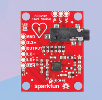
In this guide, we will learn how to interface an ECG (Electrocardiogram) sensor, specifically the AD8232 module, with the ATmega2560 development board. The AD8232 module is a specialized sensor designed to capture and measure electrical signals produced by the heart. By connecting the AD8232 module to the ATmega2560, we can monitor and analyze the ECG signals, enabling applications such as heart rate monitoring, arrhythmia detection, and biofeedback systems.
Problem Statement
The objective of this project is to interface the AD8232 ECG sensor with the ATmega2560 development board and retrieve and process the ECG signals for heart rate monitoring and analysis.
Requirements
To successfully complete this project, you will need the following components:
- ATmega2560 development board.
- AD8232 ECG sensor module.
- Micro USB cable.
- Breadboard.
- Jumper Wires.
- 16X2 LCD
Working
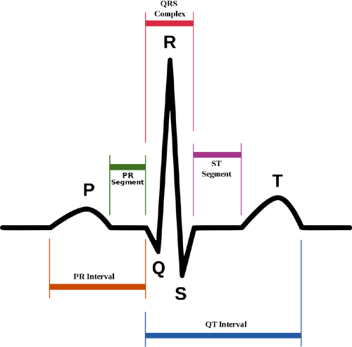
ECG or Electro Cardiography is a method to measure some important parameters of a human heart. It outputs analog values that produce a particular signal that looks as shown below.
Each interval of the signal has an optimal value range, and deviation from that might be linked to a particular disease. Here are the main parts of an ECG signal.
- P wave - It is the trailing wave on the left of the QRS complex.
- QRS complex - It is an impulse generated by ventricular contraction.
- T wave - It is a leading wave right to the QRS complex.
- U wave - It is not always observed due to its low peak value.
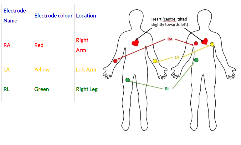
There are two placements that can be used-
Circuit Diagram
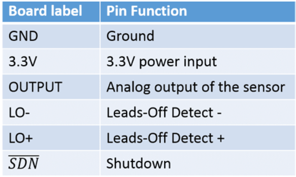
- Connect the Output pin of sensor to pin number 97, which is on 0th pin of PORT F.
- Similarly, connect LO- and LO+ to pin number 77 and 78 respectively. These pins are connected to pin 0 and 2 of PORT A.
- Finally, connect the power pins of the sensor
Too see the graph we will need to send the ADC values to a serial plotter application . Firstly, download the Better Serial Plotter for Windows from here and for Linux from here.
Code
- Open VS Code and paste the code into the file named main.c
- Additionally, add the library for UART from here into the workspace of your project, which along with the main code can be downloaded from here. (You can find main.c file where the main function is implementation)
- To compile and convert this into hex run the following command in your terminal-
avr-gcc -Wall -g -Os -mmcu=atmega2560 -o ecg_sensor.hex main.c#define F_CPU 16000000UL
#include <avr/io.h> //Defines pins, ports, etc.
#include <util/delay.h> //Defines delay functions
#include <stdio.h> //Defines sprintf function
#include <util/delay.h> //Defines delay functions
#include <stdlib.h> //Defines dtostrf function
#include <string.h> //Defines strcat function
#include "uart.c" //uart header file
float value; // variable to store ADC value
char data[20]; // buffer for uart output
int i = 0;
static inline void initADC0(void)
{
ADMUX |= (1 << REFS0); // reference voltage on AVCC
ADCSRA |= (1 << ADPS1) | (1 << ADPS0); // ADC clock prescaler /8
ADCSRA |= (1 << ADEN); // enables the ADC
}
int main(void)
{
DDRA = DDRA & (~1 << 0); // Makes of PORTA0 as Input
DDRA = DDRA & (~1 << 1); // Makes of PORTE1 as Input
initADC0(); // initialize the ADC
uart_start(); // initialize the UART
while (1)
{
if ((PINA & (1 << 0) == 1) || (PINA & (1 << 1) == 1))
{
uart_sendstr("!");
}
else
{
ADCSRA |= (1 << ADSC); // start ADC conversion
loop_until_bit_is_clear(ADCSRA, ADSC); // wait until ADC conversion is done
value = ADC;
dtostrf(value, 3, 2, data); // convert float to string
uart_sendstr(data);
}
}
return 0;
}- Now open AVRDUDES and from the Programmer (-c) dropdown select Any usbasp clone with the correct VID/PID
- In the Flash section, click on three dots and navigate to the desired hex file, and select it. Finally, click on Program to burn the hex file in the microcontroller.
- After flashing connect a USB to J14 on ATmega which gives serial output. Open the better serial plotter application and you will see the graph being plotted.
Output
After uploading the code to the ATmega2560, the program will read the ECG signal from the AD8232 sensor using the ADC. The signal will be processed and the plotted on the serial plotter.
Conclusion
By following this guide, you have successfully interfaced the AD8232 ECG sensor with the ATmega2560 development board. You can now capture and analyze ECG signals for heart rate monitoring and analysis. This project opens up possibilities for various applications in healthcare, fitness, and biofeedback systems. Enjoy exploring the capabilities of the ATmega2560 and the AD8232 ECG sensor in your projects!