Using a Servo Motor with Raspberry Pi
Introduction
Problem Statement
Controlling servo motor using a Raspberry Pi.
Requirements
To complete this project, you will need the following components:
- Raspberry Pi
- Servo motor
- Jumper wires
- Breadboard (optional)
Working
The control circuit interprets input signals, usually in the form of pulse width modulation (PWM), which specify the desired position or angle for the motor shaft. The position feedback mechanism, such as a potentiometer or an encoder, provides information about the motor's current position.
The control circuit compares the desired position with the actual position indicated by the feedback mechanism. If there is a deviation, the control circuit adjusts the motor's output to correct the difference and bring the motor to the desired position. This closed-loop control system ensures accurate and consistent positioning.
The DC motor, coupled with a gear mechanism, converts the electrical signals into rotational motion. The gear mechanism reduces speed and increases torque output, allowing for precise and controlled movement of the motor shaft.
PWM frequency is set to 50Hz, which is a common frequency used for servo motors. However, different servo motors may have different frequency requirements.
Circuit Diagram
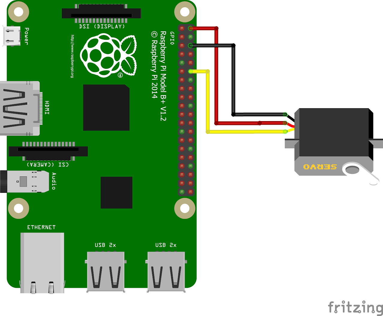
Follow the circuit diagram below to connect the servo and Raspberry Pi:
- Connect the red wire from servo motor to the PIN2 for 5V.
- Connect the black wire to PIN6 for grounding.
- Connect the yellow wire to GPIO18 (PIN12) for control.
Code
Now let's write the Python code for obtaining ECG values. Follow the steps below:
- Connect to your Raspberry Pi using VNC or Desktop environment.
- Launch the Geany Python IDE or open a text editor to write the code.
- Create a new file named
servo.pyand save the following code into it - You can copy and paste the following code from here into the file.
import RPi.GPIO as GPIO
import time

GPIO.setmode(GPIO.BCM)                    # Set up BCM GPIO numbering
GPIO.setwarnings(False)                   # disable warnings

SERVO_PIN = 18                            # GPIO18 as Servo pin
GPIO.setup(SERVO_PIN,GPIO.OUT)            # Set GPIO18 as an output
servo = GPIO.PWM(SERVO_PIN,50)            # Set PWM to 50Hz
servo.start(0)                            # Start PWM at 0% duty cycle

try:
    while(1):
        # Rotate Servo 0 to 180 degrees by changing duty cycle
        for i in range(0,180,1):
            servo.ChangeDutyCycle(2+(i/18))
            time.sleep(0.1)
            servo.ChangeDutyCycle(0)
            time.sleep(0.1)
        # Rotate Servo 180 to 0 degrees by changing duty cycle
        for i in range(180,0,-1):
            servo.ChangeDutyCycle(2+(i/18))
            time.sleep(0.1)
            servo.ChangeDutyCycle(0)
            time.sleep(0.1)

except KeyboardInterrupt:                  # If CTRL+C is pressed, exit cleanly:
    pass

servo.stop()  # Stop the PWM output
GPIO.cleanup()- After saving the file execute it by clicking on messenger like icon on geany editor or open terminal and navigate tothe folder you saved the file, execute it by typing python
servo.py
Output
The servo motor performs a continuous rotation from 0 to 180 degrees and back to 0 degrees in small increments. The servo motor moves gradually, changing its position in steps of (i/18) where 'i' represents the angle. It holds each position briefly before transitioning to the next one. This action results in a smooth back-and-forth motion of the servo motor, allowing for controlled and precise angular positioning.