Interfacing an LCD with ESP32 using ESP-IDF
Introduction
In this guide, we will demonstrate how to interface a 16x2 LCD (Liquid Crystal Display) with an ESP32 microcontroller using the ESP-IDF and the VS Code extension. The LCD will be used to display text and provide visual feedback in your ESP32 projects. We will write C code to initialize the LCD and control its operations, such as displaying text and moving the cursor. This project can be useful for creating user interfaces, data visualization, and system status displays.
Problem Statement
The objective is to interface a 16x2 LCD with an ESP32 microcontroller and control its operations using ESP-IDF for displaying text.
Requirements
To successfully complete this project, you will need the following components:
- ESP32 development board
- 16x2 LCD module (compatible with HD44780 controller)
- Jumper wires
- Breadboard
About LCD
The LCD 16x2 is a 16-pin device that comprises of 8 data pins (D0-D7) and 3 control pins (RS, RW, EN). The remaining 5 pins are used for supply and backlighting functionality of the LCD. The control pins play a vital role in configuring the LCD in either command mode or data mode, as well as determining the read or write mode.
The LCD 16x2 can be utilized in either 4-bit mode or 8-bit mode, depending on the specific requirements of the application. To use the LCD effectively, certain commands need to be sent to the LCD in command mode. Once the LCD is configured according to our requirements, we can transmit the desired data in data mode.
Circuit Diagram
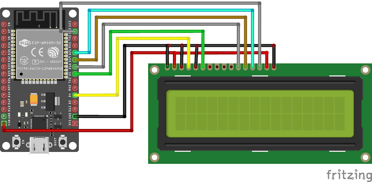
Follow the circuit diagram below to connect the LCD to the ESP32 development board:
- Connect the RS (Register Select) pin of the LCD to GPIO 4 (D4) of the ESP32.
- Connect the EN (Enable) pin of the LCD to GPIO 5 (D5) of the ESP32.
- Connect the D4 pin of the LCD to GPIO 18 (D18) of the ESP32.
- Connect the D5 pin of the LCD to GPIO 19 (D19) of the ESP32.
- Connect the D6 pin of the LCD to GPIO 21 (D21) of the ESP32.
- And connect the D7 pin of the LCD to GPIO 22 (Pin 22) of the ESP32.
- Connect the other pins of LCD as shown, we will not be using potentiometer instead we will set the LCD at lowest the contrast by grounding the concerned pins.
Code:
Now let's understand and write the C code to display characters on LCD. Follow the steps below:
- Open VS Code and create a new sample project (Follow previous guides to see how to do it).
- Now navigate to the "Main" folder and then open the Main.c file.
- Now copy and paste the following code into Main.c or download the code from here:
#include <stdio.h>
#include "sdkconfig.h"
#include "freertos/FreeRTOS.h"
#include "freertos/task.h"
#include "driver/gpio.h"
#include "driver/dac.h"
#include "esp_system.h"
#include "esp_spi_flash.h"
#include "esp_timer.h"
#include "esp_log.h"

#define LCD_PIN_RS GPIO_NUM_4
#define LCD_PIN_EN GPIO_NUM_5
#define LCD_PIN_D4 GPIO_NUM_18
#define LCD_PIN_D5 GPIO_NUM_19
#define LCD_PIN_D6 GPIO_NUM_21
#define LCD_PIN_D7 GPIO_NUM_22

#define LCD_CMD 0
#define LCD_DATA 1
#define LCD_NUM_ROWS 2
#define LCD_NUM_COLS 16

#define LCD_DELAY_MS 2

void lcd_send_nibble(uint8_t data)
{
    gpio_set_level(LCD_PIN_D4, (data >> 0) & 1);
    gpio_set_level(LCD_PIN_D5, (data >> 1) & 1);
    gpio_set_level(LCD_PIN_D6, (data >> 2) & 1);
    gpio_set_level(LCD_PIN_D7, (data >> 3) & 1);
}

void lcd_send_byte(uint8_t mode, uint8_t data)
{
    gpio_set_level(LCD_PIN_RS, mode);

    lcd_send_nibble(data >> 4);
    gpio_set_level(LCD_PIN_EN, 1);
    vTaskDelay(100 / portTICK_PERIOD_MS);
    gpio_set_level(LCD_PIN_EN, 0);

    lcd_send_nibble(data);
    gpio_set_level(LCD_PIN_EN, 1);
    vTaskDelay(100 / portTICK_PERIOD_MS);
    gpio_set_level(LCD_PIN_EN, 0);

    vTaskDelay(pdMS_TO_TICKS(LCD_DELAY_MS));
}

void lcd_send_command(uint8_t command)
{
    lcd_send_byte(LCD_CMD, command);
}

void lcd_send_data(uint8_t data)
{
    lcd_send_byte(LCD_DATA, data);
}

void lcd_init()
{
    gpio_set_direction(LCD_PIN_RS, GPIO_MODE_OUTPUT);
    gpio_set_direction(LCD_PIN_EN, GPIO_MODE_OUTPUT);
    gpio_set_direction(LCD_PIN_D4, GPIO_MODE_OUTPUT);
    gpio_set_direction(LCD_PIN_D5, GPIO_MODE_OUTPUT);
    gpio_set_direction(LCD_PIN_D6, GPIO_MODE_OUTPUT);
    gpio_set_direction(LCD_PIN_D7, GPIO_MODE_OUTPUT);

    // Wait for the LCD to power up
    vTaskDelay(pdMS_TO_TICKS(50));

    // Initialization sequence
    lcd_send_nibble(0x03);
    gpio_set_level(LCD_PIN_EN, 1);
    vTaskDelay(100 / portTICK_PERIOD_MS);
    gpio_set_level(LCD_PIN_EN, 0);

    vTaskDelay(pdMS_TO_TICKS(5));

    lcd_send_nibble(0x03);
    gpio_set_level(LCD_PIN_EN, 1);
    vTaskDelay(100 / portTICK_PERIOD_MS);
    gpio_set_level(LCD_PIN_EN, 0);

    vTaskDelay(pdMS_TO_TICKS(1));

    lcd_send_nibble(0x03);
    gpio_set_level(LCD_PIN_EN, 1);
    vTaskDelay(100 / portTICK_PERIOD_MS);
    gpio_set_level(LCD_PIN_EN, 0);

    vTaskDelay(pdMS_TO_TICKS(1));

    lcd_send_nibble(0x02);
    gpio_set_level(LCD_PIN_EN, 1);
    vTaskDelay(100 / portTICK_PERIOD_MS);
    gpio_set_level(LCD_PIN_EN, 0);

    vTaskDelay(pdMS_TO_TICKS(1));

    // Function set: 2 lines, 5x8 dots
    lcd_send_command(0x28);
    // Display on, cursor off, blink off
    lcd_send_command(0x0C);
    // Entry mode set: increment mode, no shift
    lcd_send_command(0x06);

    // Clear the display
    lcd_send_command(0x01);
    vTaskDelay(pdMS_TO_TICKS(2));
}

void lcd_set_cursor(uint8_t row, uint8_t col)
{
    uint8_t command = 0x80;
    if (row == 1)
        command |= 0x40;
    command += col;
    lcd_send_command(command);
    printf("Set cursor to row %d, col %d\n", row, col);
}

void lcd_print(const char *str)
{
    while (*str)
    {
        lcd_send_data(*str++);
    }
}

void app_main()
{
    lcd_init();
    lcd_set_cursor(0, 0);
    lcd_print("Welcome to Lab");
    lcd_set_cursor(1, 0);
    lcd_print("in a box! :D");
}- Now at the bottom navbar of VS Code select the port, flash method and click on the Build, flash and monitor icon.
Note: During the flashing process of your board, you may encounter an error. If this happens, there's no need to worry. Simply flash the board again and when you see the message "connecting..........." appear, press and hold the boot button on your board for 1 or 2 seconds. Keep holding it until the dots on the screen start disappearing or the further flashing process begins. This action will help resolve any issues and ensure a successful flashing of your board.
Output
After flashing the code to the ESP32, the LCD will display "Welcome to Lab in a Box! 😄 ".
Conclusion
Congratulations! You have successfully interfaced an LCD with an ESP32 using the provided code. You can now customize the code to display different messages or experiment with other LCD functionalities. This project opens up possibilities for creating user interfaces, displaying sensor data, and providing visual feedback in ESP32-based projects. Try different texts and characters.