Controlling Fan Speed with Raspberry Pi using Pulse Width Modulation
Introduction
Problem Statement
The objective is to control the speed of a fan connected to a Raspberry Pi using PWM and a motor driver module.
Requirements
To complete this project, you will need the following components:
- Raspberry Pi
- Fan (DC fan)
- L298N Motor driver module
- Power supply for the motor driver (5V)
- Jumper wires
Working
Pulse Width Modulation (PWM) is a technique used to control the average voltage or power supplied to a device by rapidly switching it ON and OFF. It works by varying the width or duration of the ON state (duty cycle) while keeping the frequency constant.
In the case of fan speed control, PWM is used to adjust the voltage supplied to the fan motor by adjusting the duty cycle of the PWM signal. By increasing or decreasing the duty cycle, we can effectively control the average power supplied to the fan motor, thus controlling its speed.
Why Motor Driver is Required and How it Works:
The goal is to control the speed of a fan connected to a Raspberry Pi using PWM. However, as the Raspberry Pi's GPIO pins cannot provide the required voltage directly, we will use a motor driver module to drive the fan motor effectively. The motor driver module, such as the L298N, is used to provide the necessary power and control signals to drive the fan motor effectively.
The L298N, is a popular dual H-bridge module capable of driving DC motors. It has input pins (in3_pin and in4_pin) to control the direction of rotation of the motor, and an enable pin (enable_pin) to control the motor's speed. (In this guide, we will only focus on speed and not direction)
By adjusting the PWM duty cycle, we vary the average power supplied to the fan motor. The motor driver module, connected to the enable pin, takes the PWM signal from the Raspberry Pi and adjusts the voltage supplied to the fan motor accordingly, thus controlling its speed.
Since we will be controlling speed only, we will connect the in4 pin of the motor driver to the pin next to enB (enable_B) pin. This pin is a 5v pin which would make sure that in4 is high and in3 would be low as it is not connected to anything. So in this case, direction will be forward.
Circuit Diagram
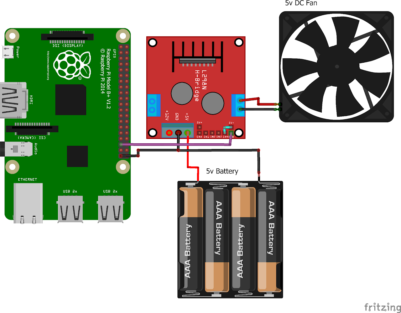
Follow the circuit diagram below to connect the fan, motor driver module, and Raspberry Pi:
- First of all connect the 5v Battery to the motor driver.
- Short the 5V pin and IN4 of the motor driver.
- Connect the Fan to equivalent output terminal of driver
- Connect the ENB/ENA to GPIO19 (Pin 35) of RPi
Code
Now let's write the Python code for obtaining ECG values. Follow the steps below:
- Connect to your Raspberry Pi using VNC or Desktop environment.
- Launch the Geany Python IDE or open a text editor to write the code.
- Create a new file named
pwm_fan.pyand save the following code into it - You can copy and paste the following code from here into the file.
import RPi.GPIO as GPIO
import time

GPIO.setmode(GPIO.BCM)            # Set up BCM GPIO numbering
FAN_PIN = 19                      # GPIO19 as FAN Pin
GPIO.setup(FAN_PIN, GPIO.OUT)     # Set GPIO as output
FAN = GPIO.PWM(FAN_PIN, 100)      # Set Frequency to 100Hz
FAN.start(0)                      # Start PWM output, Duty Cycle = 0

try:
    while (1):                   # Loop until keyboard interrupt
        # Increase duty cycle: 0~50
        for x in range(50):
            FAN.ChangeDutyCycle(x)
            time.sleep(0.1)
        # Decrease duty cycle: 50~0
        for x in range(50):
            FAN.ChangeDutyCycle(50-x)
            time.sleep(0.1)
except KeyboardInterrupt:
    pass

FAN.stop()
GPIO.cleanup()- After saving the file execute it by clicking on messenger like icon on geany editor or open terminal and navigate tothe folder you saved the file, execute it by typing
python pwm_fan.py
Output
Upon running the code, the fan connected to the motor driver will start running. The code gradually increases the duty cycle of the PWM signal from 0 to 50%, thereby increasing the fan speed. After reaching the maximum duty cycle, it gradually decreases the duty cycle back to 0, thereby decreasing the fan speed. The loop continues until a keyboard interrupt (Ctrl+C) is detected.