Interfacing a DC Motor with the ATmega2560 Development Board
Introduction
In this guide, we will learn how to interface a DC motor with the ATmega2560 development board using the onboard L293D motor driver and embedded C code. The L293D is a popular motor driver IC that allows easy control of DC motors.
Requirements
To successfully complete this project, you will need the following components:
- ATmega2560 development board.
- BME280 Sensor.
- DC Motors.
- Jumper Wires.
Working
A motor driver is an electronic device that controls the operation of an electric motor by providing the necessary power and signals. Its precise working can be summarized as follows:
- Power amplification: The motor driver receives control signals from a motor controller or a microcontroller. These signals are usually low-power signals, so the motor driver amplifies them to provide sufficient power to drive the motor effectively.
- Pulse-width modulation (PWM): Many motor drivers use PWM techniques to control the motor's speed. PWM involves rapidly switching the power supply on and off at varying duty cycles. By adjusting the duty cycle, the motor driver controls the effective voltage and, therefore, the motor's speed.
- Direction control: For motors that require bidirectional rotation, such as DC motors, the motor driver controls the direction by reversing the polarity of the voltage applied to the motor's terminals. This is achieved through appropriate switching mechanisms within the driver circuitry.
Circuit Diagram
Follow the circuit diagram below to control the motors using the development board:
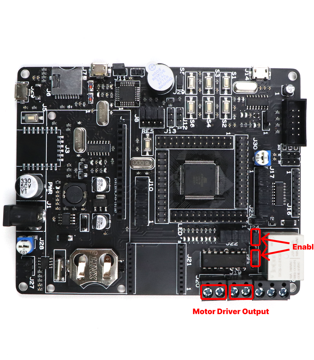
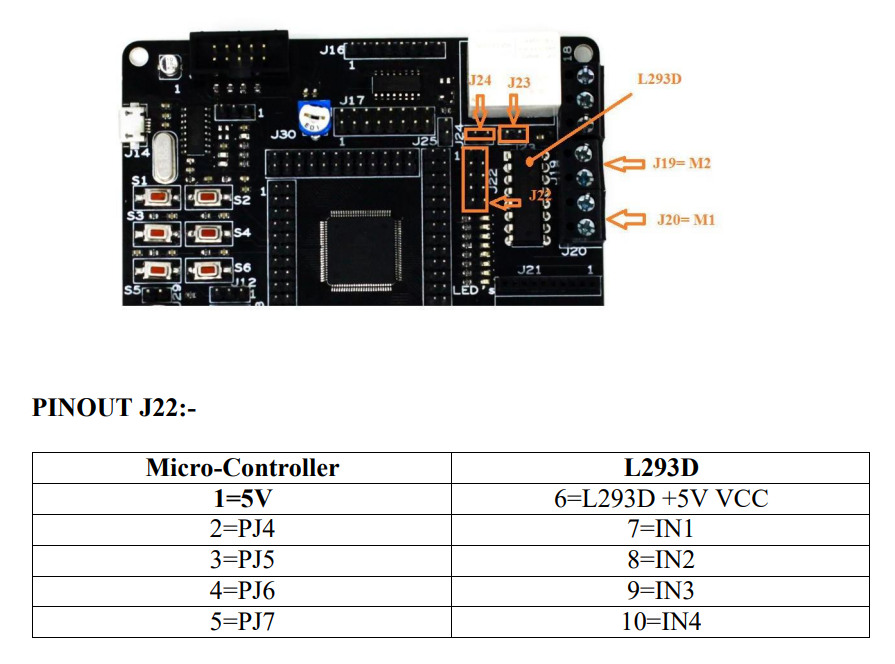
- Remove the jumper J23 to connect EN of motor driver pin to OC4A pin of the controller, i.e. pin 3 of the Port H (external pin 15), for more refer to this.
- Connect motor terminals to Motor driver output (j20).
Code
- Open VS Code and paste the code into the file named dc_motor.c
- To compile and convert this into hex run the following command in your terminal-
avr-gcc -Wall -g -Os -mmcu=atmega2560 -o dc_motor.hex dc_motor.cYou can download the code from here.
#ifndef F_CPU
#define F_CPU 16000000UL // set the CPU clock
#endif
#include <avr/io.h>     /* Include AVR std. library file */
#include <stdio.h>      /* Include std. library file */
#include <util/delay.h> /* Include Delay header file */

int main(void)
{
    DDRJ = DDRJ | (1 << PJ4);
    DDRJ = DDRJ | (1 << PJ5);
    DDRJ = DDRJ | (1 << PJ6);
    DDRJ = DDRJ | (1 << PJ7);
    DDRH |= (1 << PH3); /* Make OC4A pin as output */
    TCNT4 = 0;          /* Set timer4 count zero */
    ICR4 = 2499;        /* Set TOP count for timer4 in ICR4 register */
    /* Set Fast PWM, TOP in ICR4, Clear OC4A on compare match, clk/64 */
    TCCR4A = (1 << WGM11) | (1 << COM1A1);
    TCCR4B = (1 << WGM12) | (1 << WGM13) | (1 << CS10) | (1 << CS11);
    while (1)
    {
        OCR4A = 1000;
        PORTJ = PORTJ | (1 << PJ4);
        PORTJ = PORTJ & ~(1 << PJ5);
        _delay_ms(1000);
        OCR4A = 2000;
        PORTJ = PORTJ | (1 << PJ5);
        PORTJ = PORTJ & ~(1 << PJ4);
        _delay_ms(1000);
    }
}- Now open AVRDUDES and from the Programmer (-c) dropdown select Any usbasp clone with the correct VID/PID
- In the Flash section, click on three dots and navigate to the desired hex file, and select it. Finally, click on Program to burn the hex file in the microcontroller.
Output
Upon successful upload and execution of the code, the DC motor connected to the output pins will rotate in a forward direction in slow speed for 1 second, followed by a backward rotation for 1 second with fast speed, This sequence will continue in an infinite loop.
Conclusion
Interfacing a DC motor with the ATmega2560 development board using the L293D motor driver allows you to control the motor's direction and speed. By following the steps outlined in this guide and understanding the provided code, you should be able to successfully interface and control a DC motor using the ATmega2560 development board and L293D motor driver. Experiment with different OCR4A values, delay times, and motor connections to achieve the desired motor behavior for your specific project requirements.