Interfacing DC Motor with P89V51RD2
Introduction
A DC motor is an electrical motor that converts direct current electrical energy into mechanical energy. The most common types rely on the forces produced by induced magnetic fields due to flowing current in the coil. Nearly all types of DC motors have some internal mechanism, either electromechanical or electronic, to periodically change the direction of current in a part of the motor.
Problem Statement
The objective is to interface a DC Motor with 8051, and write a program such that when 1st push button is pressed motor speed increases, and when released motor speed remains same, when 2nd push button is pressed motor speed decreases, and when 3rd push button is pressed, motor changes direction.
Requirements
- P89V51RD2
- Breadboard
- DC Motor
- Motor Driver
- Jumper wires
- Push Button
- Resistors
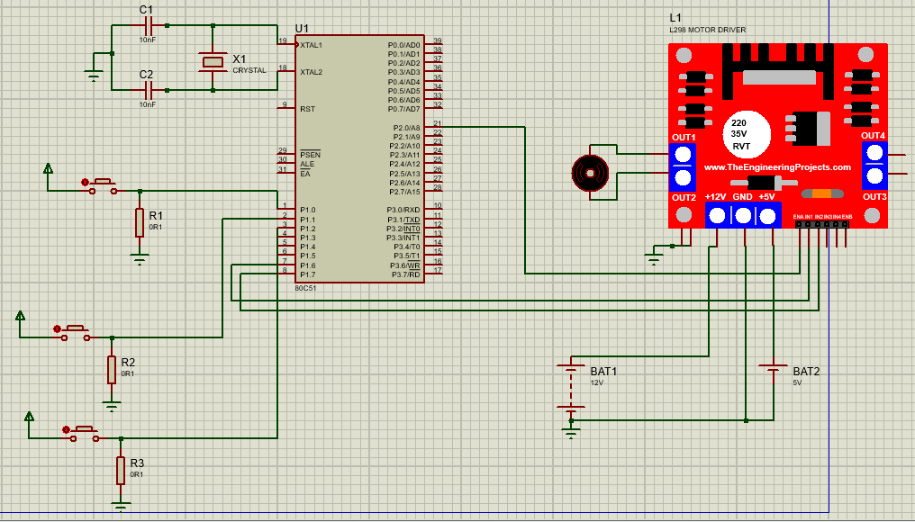
Circuit Diagram
Code
- Copy and paste the following code into main.c or download it from here:
c
#include <reg51.h>
#include <intrins.h>
#define PWM_Period 0xB7FE  // Define value to be loaded in timer for PWM period of 20 milli second

sbit PWM_Out_Pin    = P2^0; // PWM Out Pin for speed control
sbit Speed_Inc      = P1^0; // Speed Increment switch pin
sbit Speed_Dec      = P1^1; // Speed Decrement switch pin
sbit Change_Dir     = P1^2; // Rotation direction change switch pin

sbit M1_Pin1        = P1^6; //Motor Pin 1
sbit M1_Pin2        = P1^7; // Motor Pin 2

unsigned int ON_Period, OFF_Period, DutyCycle, Speed;


// Function to provide delay of 1ms at 11.0592 MHz
void delay(unsigned int count)
{
    int i,j;
    for(i=0; i<count; i++)
            for(j=0; j<112; j++);
}

void Timer_init()
{
    TMOD = 0x01;        //Timer0 mode1
    TH0 = (PWM_Period >> 8);// 20ms timer value
    TL0 = PWM_Period;
    TR0 = 1;        // Start timer0
}

// Timer0 interrupt service routine (ISR)
void Timer0_ISR() interrupt 1
{
    PWM_Out_Pin = !PWM_Out_Pin;
    if(PWM_Out_Pin)
    {
        TH0 = (ON_Period >> 8);
        TL0 = ON_Period;
    }
    else
    {
        TH0 = (OFF_Period >> 8);
        TL0 = OFF_Period;
    }
}

// Calculate ON & OFF period from PWM period & duty cycle
void Set_DutyCycle_To(float duty_cycle)
{
    float period = 65535 - PWM_Period;
    ON_Period = ((period/100.0) * duty_cycle);
    OFF_Period = (period - ON_Period);
    ON_Period = 65535 - ON_Period;
    OFF_Period = 65535 - OFF_Period;
}

// Initially Motor Speed & Duty cycle is zero and in either direction
void Motor_Init()
{
    Speed = 0;
    M1_Pin1 = 1;
    M1_Pin2 = 0;
    Set_DutyCycle_To(Speed);
}

int main()
{
  EA  = 1;          // Enable global interrupt
  ET0 = 1;              // Enable timer0 interrupt
  Timer_init();
  Motor_Init();
  while(1)
    {
    // Increment Duty cycle i.e. speed by 10% for Speed_Inc Switch
    if(Speed_Inc == 1)
        {
            if(Speed < 100)
            Speed += 10;
            Set_DutyCycle_To(Speed);
            while(Speed_Inc == 1);
            delay(200);
        }
    // Decrement Duty cycle i.e. speed by 10% for Speed_Dec Switch
    if(Speed_Dec == 1)
        {
            if(Speed > 0)
            Speed -= 10;
            Set_DutyCycle_To(Speed);
            while(Speed_Dec == 1);
            delay(200);
        }
    // Change rotation direction for Change_Dir Switch
    if(Change_Dir == 1)
        {
            M1_Pin1 = !M1_Pin1;
            M1_Pin2 = !M1_Pin2;
            while(Change_Dir == 1);
            delay(200);
        }
    }
}
Output
DC Motor doesn't rotate until the first (connected to P1.0)push button is pressed. When the first push button is pressed the speed of the motor increases i.e. whenever the push button is pressed its speed increases and when the push button is released the motor continues to rotate at the same speed. The speed can be increased up to a certain value. The second(connected to P1.1) push button is for reducing the speed of the motor. The third(connected to P1.2) push button is for changing the direction of the motor.
Conclusion
By following this guide and utilizing the provided code, you have acquired the knowledge to control a DC motor using a P89V51RD2. The P89V51RD2 microcontroller generates pulse width modulation (PWM) signals, enabling you to exert precise control over the DC motor's speed by adjusting the PWM. By experimenting with various pulse durations and time intervals, you can achieve the desired speed of the dc motor for your specific application requirements. DC motors are used in elevators, steel mills, rolling mills, locomotives, and excavators, in which the P89V51RD2 and dc motor combination offer a versatile platform for achieving accurate and controlled motion. With the ability to fine-tune the pulse width, you can customize the dc motor's behavior to suit your project's needs.