Controlling an LED with a Push Button using ESP32 and ESP-IDF
Introduction
In this guide, we will explore how to interface a push button with an LED using the ESP32 development board. By connecting a push button and an LED to the ESP32, we can create a simple but effective user interface, where pressing the button will toggle the LED on and off.
Problem Statement
The goal is to create a circuit that allows us to control an LED using a push button. When the button is pressed, the LED should turn on, and when the button is released, the LED should turn off.
Requirements
To successfully complete this project, you will need the following components:
- ESP32 development board
- Push button
- Resistor
- LED
- Jumper wires
- Breadboard
Circuit Diagram
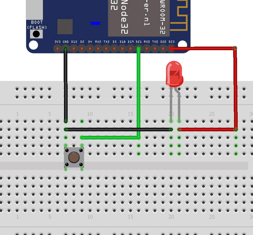
Follow the circuit diagram below to connect the push button, LED and ESP32 development board:
- Connect one leg of the push button to GPIO2 (pin D2) on the ESP32.
- Connect the other leg of the push button to GND (ground) on the ESP32.
- The positive (anode) leg of the LED to GPIO4 (pin D4) on the ESP32.
- Connect the negative (cathode) leg of the LED to GND (ground) on the ESP32.
Code:
Now let's understand and write the C code to control the brightness of LED. Follow the steps below:
- Open VS Code and create a new sample project with the name push_button (Follow previous guides to see how to do it).
- Now navigate to the "Main" folder of the project and then open the Main.c file.
- Copy and paste the following code into Main.c or download the code from here:
#include <stdio.h>
#include "driver/gpio.h"
#include "freertos/FreeRTOS.h"
#include "freertos/task.h"
#include "esp_log.h"

void app_main(void)
{
    // Intialise GPIO2 as input for button
    gpio_set_direction(GPIO_NUM_21, GPIO_MODE_INPUT);
    gpio_set_pull_mode(GPIO_NUM_21, GPIO_PULLUP_ONLY);

    // Intialise GPIO4 as output for LED
    gpio_set_direction(GPIO_NUM_23, GPIO_MODE_OUTPUT);

    while (true)
    {
        // If button is pressed, turn on LED
        if (gpio_get_level(GPIO_NUM_21)==0)
        {
            gpio_set_level(GPIO_NUM_23, 1);
            printf("Button Pressed\n");
        }
        else
        {
            gpio_set_level(GPIO_NUM_23, 0);
        }

        vTaskDelay(10);
    }
}- Now at the bottom navbar of VS Code select the port, flash method and click on the Build, flash and monitor icon.
Note: During the flashing process of your board, you may encounter an error. If this happens, there's no need to worry. Simply flash the board again and when you see the message "connecting..........." appear, press and hold the boot button on your board for 1 or 2 seconds. Keep holding it until the dots on the screen start disappearing or the further flashing process begins. This action will help resolve any issues and ensure a successful flashing of your board.
Output
After successfully uploading the code, the LED connected to GPIO4 will glow when the button is pressed, indicating that the button is pressed. The console output (IDF Monitor) will also display the message "Button Pressed" to indicate that the button press event is detected.
Conclusion
In this project, you have successfully interfaced a push button with an LED using the ESP32 microcontroller. This project can serve as a foundation for more complex applications involving user input and output interactions. You can explore additional functionalities such as debouncing the button, implementing different LED patterns