Getting Started
Introduction
Congratulations on starting your journey with ESP-IDF (Espressif IoT Development Framework)! ESP-IDF is a powerful framework that allows you to develop applications for the ESP32 microcontroller board. In this tutorial, we will walk you through setting up your first ESP-IDF project on VS Code, allowing you to leverage the full potential of ESP-IDF. Together, we will write a simple program to blink an LED, providing you with a solid foundation to create exciting projects using your ESP32 board. Let's dive into the world of ESP-IDF and unleash your creativity in the realm of IoT development!
Problem Statement
The objective is to control the blinking of an LED using ESP-IDF on your ESP32.
Requirements
To complete this project, you will need the following components:
- ESP32 development board
- LED
- Resistor (220 ohms)
- Breadboard
- Jumper wires
Circuit Diagram
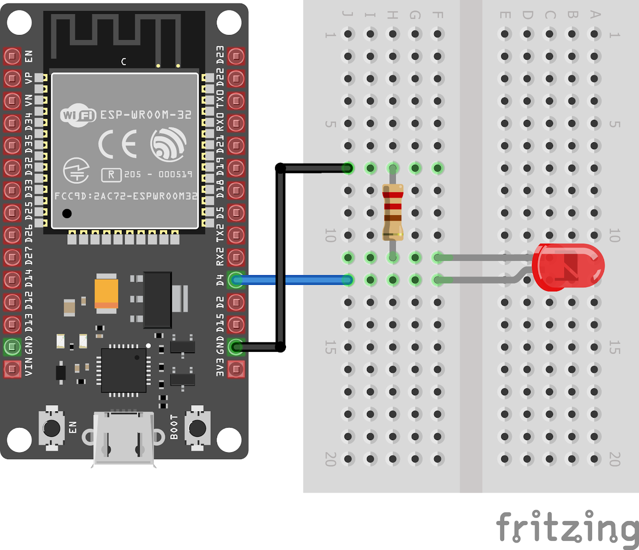
Follow the circuit diagram below to connect the LED to the ESP32 development board:
- Connect the anode (long leg) of the LED to GPIO pin 4 (LED_PIN) of the ESP32.
- Connect the cathode (short leg) of the LED to a resistor (220 ohms).
- Now connect the other end of the resistor to the ground (GND) pin of the ESP32.
Code
Now let's understand and write the C code to control the LED. Follow the steps below:
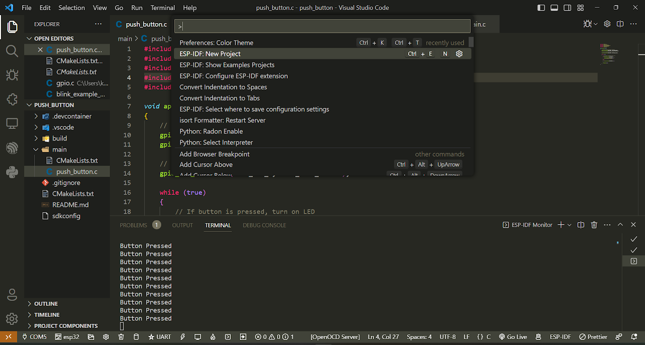
- Open VS Code and go to View > Command Palette (Ctrl + Shift + P). Type "ESP-IDF: New Project" in the search bar and press Enter.
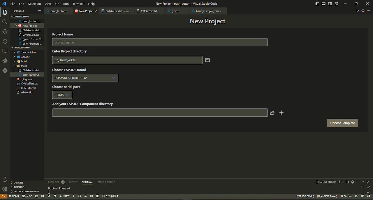
- Specify the project name and directory. Choose a meaningful name for your project, such as "Blink_Led". Choose the ESP-IDF board by selecting the "ESP-WROVER-KIT 3.3V" option. Click the "Choose Template" button to proceed.
- In the Extensions view, select the ESP-IDF option. You will see a list of available templates. Under the "get-started" tab, click on the "sample_project" template.
- Then click "Create project using template sample_project".
- A notification will appear, indicating that the project has been created. You can choose to open the project in a new window by clicking "Yes".
- Now navigate to the "Main" folder and then open the Main.c file.
- You might also see other files like CMakeLists.txt this is the config file for building the project the SRCS "main.c" part tells the CMake compiler about source files of the project, similarly INCLUDE_DIRS "." part is for any header files that would be used.
- Now copy and paste the following code into Main.c or download the code from here:
// Code for led blinking
#include <stdio.h>
#include "esp_log.h"
#include "freertos/FreeRTOS.h"
#include "freertos/task.h"
#include "driver/gpio.h"
#define LED_PIN GPIO_NUM_4

void app_main(void)
{
    // set the LED pin as output
    gpio_set_direction(LED_PIN, GPIO_MODE_OUTPUT);
    // turn on the led
    gpio_set_level(LED_PIN, 1);

    while (1)
    {
        // Turn off the led for 1 second
        gpio_set_level(LED_PIN, 0);
        vTaskDelay(1000 / portTICK_PERIOD_MS); // 1000 ms delay
        // Turn on the led for 1 second
        gpio_set_level(LED_PIN, 1);
        vTaskDelay(1000 / portTICK_PERIOD_MS); // 1000 ms delay
    }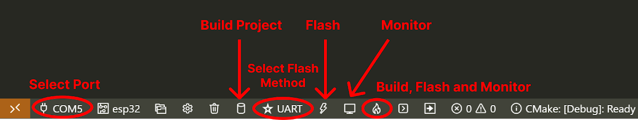
}- Now at the bottom navbar of VS Code select the port of your ESP32 on the left side.
- After selecting port select the target device besides port, now select the flash method by clicking on star icon and select the UART option and the workspace.
- Finally, it's time to compile and flash the code. Click on the fire like icon in the bottom navbar. Your project will start compiling
Note: When your board is getting flashed, you might encounter an error, do not worry just re-click the Build, Flash and Monitor icon again and when you see the following line "connecting..........." press boot button (of ESP32) for 1 or 2 seconds until the dots start disappearing or further flashing part starts.
Output
After flashing the code to the ESP32, the LED connected to the GPIO pin 4 (LED_PIN) should start blinking. The LED will be turned on for one second and then turned off for one second repeatedly.
Conclusion
Congratulations! You have successfully learned how to create a custom project in ESP-IDF and control an LED using ESP-IDF. By leveraging the ESP32's GPIO pins and writing code using the ESP-IDF framework, you can create a wide range of exciting projects. Feel free to experiment with different time intervals and explore further possibilities to expand your IoT development skills. Happy coding!