LED Chaser with the LPC2148 Development Board
Introduction
Problem Statement
Requirements
To successfully complete this project, you will need the following components:
We will program the on-board led D1, D2, D3 and D4 connected to 16th, 17th, 18th and 19th pin of port 1.
USB cables, for power and programming.
Code
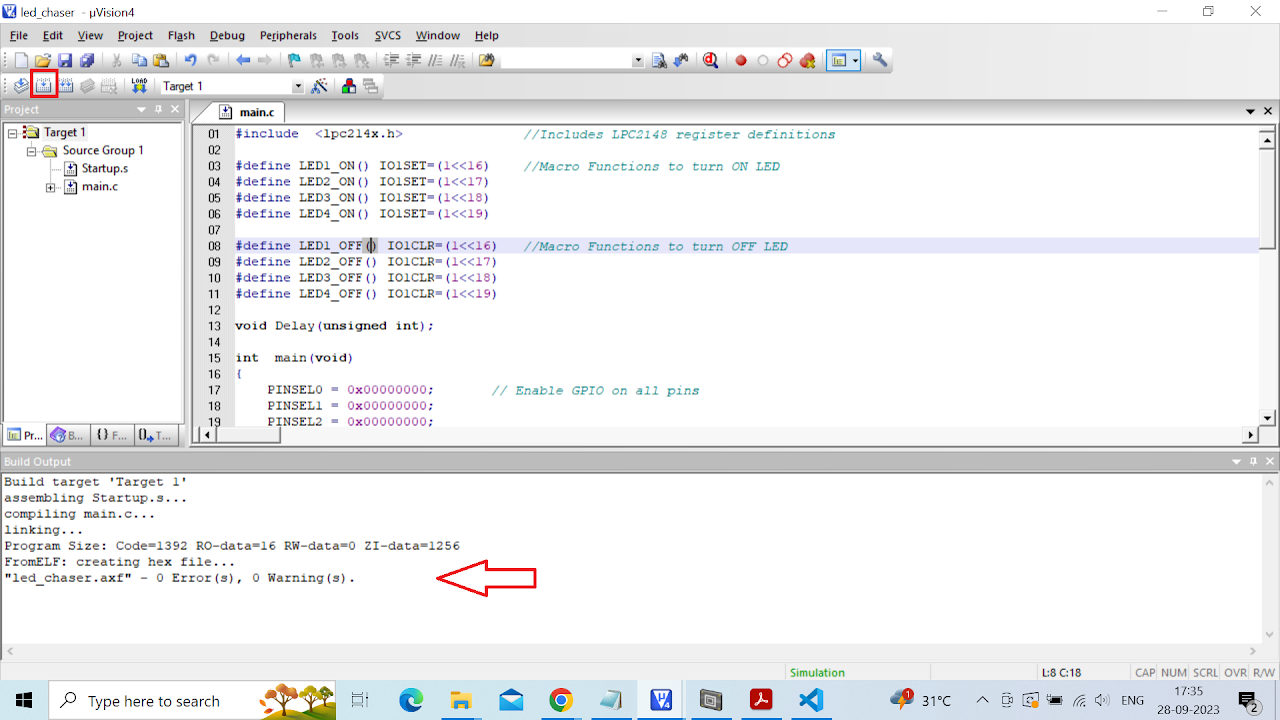
Open the Keil IDE and create a new project with name chaser_led by clicking on project in the menu bar. (Refer the steps from Getting started page to create new project - do not skip any step from the process)
Copy the code given below into the main.c file and save the main.c file. You can also copy and paste the code from here into the file.
#include  <lpc214x.h>               //Includes LPC2148 register definitions

#define LED1_ON() IO1SET=(1<<16)    //Macro Functions to turn ON LED
#define LED2_ON() IO1SET=(1<<17)
#define LED3_ON() IO1SET=(1<<18)
#define LED4_ON() IO1SET=(1<<19)

#define LED1_OFF() IO1CLR=(1<<16)   //Macro Functions to turn OFF LED
#define LED2_OFF() IO1CLR=(1<<17)
#define LED3_OFF() IO1CLR=(1<<18)
#define LED4_OFF() IO1CLR=(1<<19)

void Delay(unsigned int);

int  main(void)
{
    PINSEL0 = 0x00000000;       // Enable GPIO on all pins
    PINSEL1 = 0x00000000;
    PINSEL2 = 0x00000000;

    IO1DIR = (1<<19) | (1<<18) | (1<<17) | (1<<16);     // Set P1.16, P1.17, P1.18, P1.19 as Output
    while(1)
    {
        LED1_ON();
        Delay(100);
        LED1_OFF();
        LED2_ON();
        Delay(100);
        LED2_OFF();
        LED3_ON();
        Delay(100);
        LED3_OFF();
        LED4_ON();
        Delay(100);
        LED4_OFF();
    }
}


void Delay (unsigned int ms)
{
    unsigned int i, j;
    for (j = 0; j < (ms / 10); j++)
    {
        for (i = 0; i < 60000; i++);
    }
}- After saving the file click on build icon or press F7. You should be able to see the build output with 0 errors and warnings.
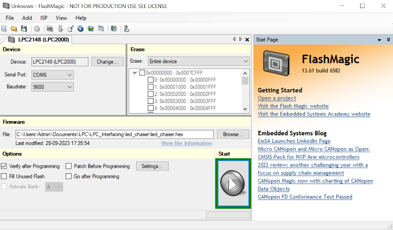
Now the hex file has been generated i.e. your program is compiled for uploading on the board. Open Flash Magic and do the following changes:
a. Change the Device to LPC2148
b. Select the Serial Port
c. Change the baud rate to 9600
d. Finally in the firmware section select the generated hex file.
e. In the erase section select entire device (refer the image below).
To upload the code do the following:
i. Connect a DB9 cable between the selected COMx port on your PC and the UART0 port on LPC2148 development board.
ii. Plug in an AC/DC 9V/1A supply to the development board and slide ON/OFF switch to ON position.
iii. Enter in to boot load mode by keeping the BOOT switch pressed and then press RESET switch.
iv. You should see LED D4 glowing which means board is now in programming mode.
Click on Start in the Flash Magic tool. This will upload the code to the board.
- Once you have uploaded the code into board then exit the programming mode by pressing reset button once.
Output
Upon successfully running the project, the built-in LEDs will turn on and off in a sequential pattern. The chaser pattern demonstrates successful code execution and showcases the functionality of the board.
Conclusion
In this guide, you have learned how to build LED chaser on the LPC2148 development board using built-in LEDs. This experiment involved utilizing the GPIO pins of the LPC2148 microcontroller to control a sequence of LEDs, creating an engaging LED chaser effect.