Interfacing Servo Motor with P89V51RD2
Introduction
More details about working of Servo: Download
Problem Statement
The objective of this project is to interface a servo motor with 8051 and write a program to continuously rotate servo motor from 0 to 180 degrees and back to 0 degrees.
Requirements
- P89V51RD2
- Servo motor
- Jumper wires
Working
The control circuit interprets input signals, usually in the form of pulse width modulation (PWM), which specifies the desired position or angle for the motor shaft. The position feedback mechanism, such as a potentiometer or an encoder, provides information about the motor's current position.
The control circuit compares the desired position with the actual position indicated by the feedback mechanism. If there is a deviation, the control circuit adjusts the motor's output to correct the difference and bring the motor to the desired position. This closed-loop control system ensures accurate and consistent positioning.
The DC motor, coupled with a gear mechanism, converts the electrical signals into rotational motion. The gear mechanism reduces speed and increases torque output, allowing for precise and controlled movement of the motor shaft.
PWM frequency is set to 50Hz, which is a common frequency used for servo motors. However, different servo motors may have different frequency requirements.
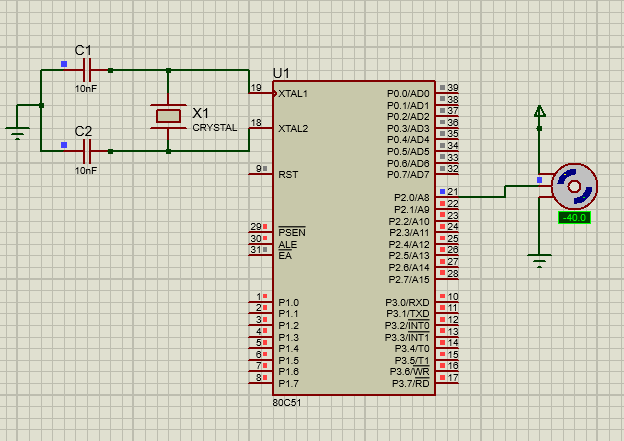
Circuit Diagram
Code
- Copy and paste the following code into main.c or download it from here:
#include <reg51.h>
#define PWM_Period 0xB7FE   //Define value to be loaded in timer for PWM period of 20 milli second
sbit Servo_Motor_Pin = P2^0;
unsigned int ON_Period, OFF_Period, DutyCycle;

void delay(unsigned int count) //delay function for 1ms
{
    int i,j;
    for(i=0; i<count; i++)
      for(j=0; j<112; j++);
}

void Timer_init()
{
  TMOD = 0x01;                   //timer0 mode1
  TH0 = (PWM_Period >> 8);       //20ms timer value
  TL0 = PWM_Period;
  TR0 = 1;                       //start timer0
}

void Timer0_ISR() interrupt 1   //timer 0 interrupy service routine(ISR)
{
  Servo_Motor_Pin = !Servo_Motor_Pin;
  if(Servo_Motor_Pin)
  {
    TH0 = (ON_Period >> 8);
    TL0 = ON_Period;
  }
  else
  {
    TH0 = (OFF_Period >> 8);
    TL0 = OFF_Period;
  }
}

void Set_DutyCycle_To(float duty_cycle)  //calculate on and off period from duty cycle
{
  float period = 65535 - PWM_Period;
  ON_Period = ((period/100.0) * duty_cycle);
  OFF_Period = (period - ON_Period);
  ON_Period = 65535 - ON_Period;
  OFF_Period = 65535 - OFF_Period;
}

int main()
{
   EA  = 1;                 //enable global interrupt
   ET0 = 1;                 //enable timer0 interrupt
   Timer_init();
   while(1)
    {
  Set_DutyCycle_To(2.7);    //0.54ms(2.7%) of 20ms(100%) period
  delay(1000);
  Set_DutyCycle_To(7);     //1.4ms(7%) of 20ms(100%) period
  delay(1000);
  Set_DutyCycle_To(12);    //2.4ms(12%) of 20ms(100%) period
  delay(1000);
    }
}