Interfacing DC Motor with the LPC2148 Development Board
Introduction
Problem Statement
Requirements
To successfully complete this project, you will need the following components:
- LPC2148 Development board
- DC Motor
- 2 USB cables, for power and programming.
Circuit Connections
For interfacing DC motors, L293D Motor driver IC is already provided on the Board. Following figure shows the connections for the L293D with motors: 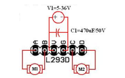
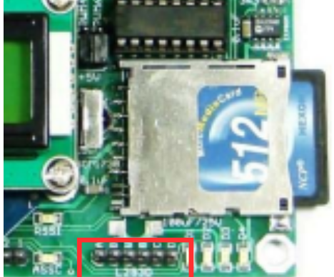
The velocity of the DC motor can varied using the PWM peripheral on the LPC2148 microcontroller or it can be fixed to maximum velocity by connecting 5V to velocity pins. For this purpose LPC2148 development board has a header for selecting the source of velocity signal.
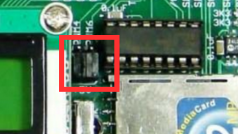
Keep the jumper position towards +5V to provide Vcc on the enable pins as shown in the figure.
Code
Open the Keil IDE and create a new project with name dc_motor by clicking on project in the menu bar. (Refer the steps from Getting started page to create new project - do not skip any step from the process)
Copy the code given below into the main.c file and save the main.c file. You can also copy and paste the code from here into the file.
#include  <lpc214x.h>

#define M1_MASK 0x00090000
#define M2_MASK 0x00060000

void  Delay(unsigned char j)
{
    unsigned int  i;
    for(;j>0;j--)
    {
        for(i=0; i<60000; i++);
    }
}

void M1_Forward()
{
    IO1CLR=M1_MASK;
    IO1SET=0x00080000;
}

void M1_Reverse()
{
    IO1CLR=M1_MASK;
    IO1SET=0x00010000;
}
void M1_Stop()
{
    IO1CLR=M1_MASK;
}

void M2_Forward()
{
    IO1CLR=M2_MASK;
    IO1SET=0x00040000;
}

void M2_Reverse()
{
    IO1CLR=M2_MASK;
    IO1SET=0x00020000;
}

void M2_Stop()
{
    IO1CLR=M2_MASK;
}

int main(void)
{
    PINSEL0 = 0x00000000;       // Enable GPIO on all pins
    PINSEL1 = 0x00000000;
    PINSEL2 = 0x00000000;
    IO1DIR = (1<<19) | (1<<18) | (1<<17) | (1<<16);     // Set P1.16, P1.17, P1.18, P1.19 as Output

    while(1)
    {
        M1_Forward();
        M2_Forward();
        Delay(100);

        M1_Stop();
        M2_Stop();
        Delay(100);

        M1_Reverse();
        M2_Reverse();
        Delay(100);

        M1_Stop();
        M2_Stop();
        Delay(100);
    }
}
Output
Upon successful execution of the program, your motors will rotate clockwise and counterclockwise with a 100ms delay.
Conclusion
By following this guide, you have successfully interfaced a DC motor with the LPC2148 development board. You can now control the direction of the motor using in-built motor driver of LPC2148 board. This opens up possibilities for various applications involving motion control.