Getting Started
Introduction
Problem Statement
Requirements
To successfully complete this project, you will need the following components:
- LPC2148 Development board
- 2 USB cables, for power and programming.
Circuit Diagram
We will program the on-board led D1 connected to 16th pin of port 2.
Creating New Project
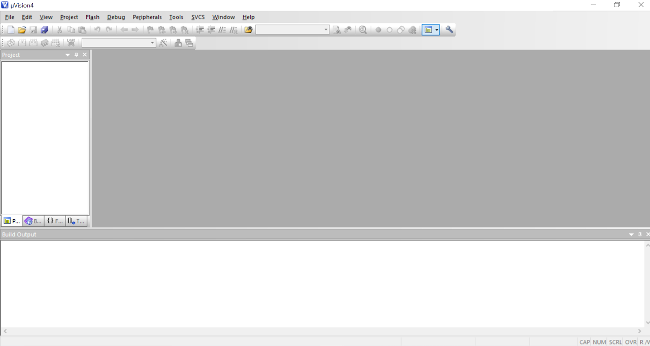
To start Keil IDE click Start>Programs>Keil μVision4. The initial screen will appear followed by the main window.
The Keil IDE main window in basic configuration is mainly divided into three areas.
- Editor - It is the area where .c and .h files of the project are edited.
- Project Explorer- It shows the project tree.
- Output Window- This window shows the messages related to compiling, project building and debugging.
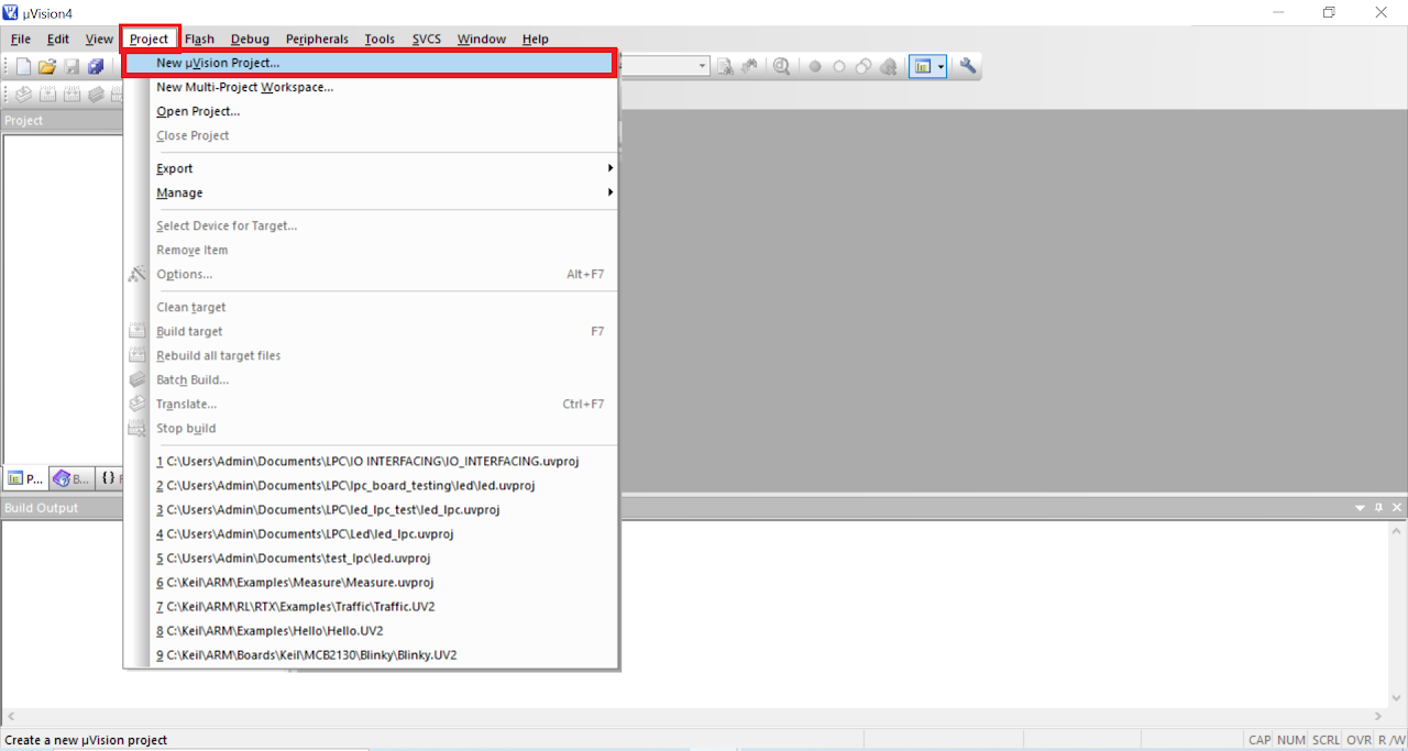
- To create a new project, Select Project>New uVision Project from the main menu.
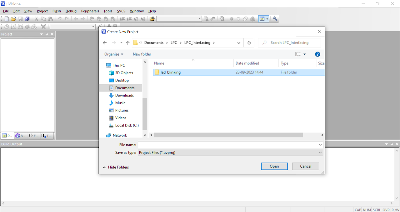
- Create a new folder and name it as led_blinking. Click Open to enter in to this directory.
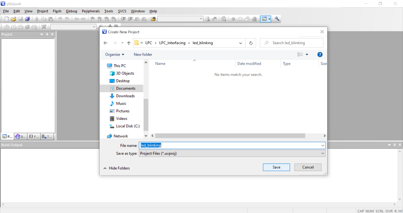
- Inside this directory create a new project and name it as led_blinking and click Save to continue.
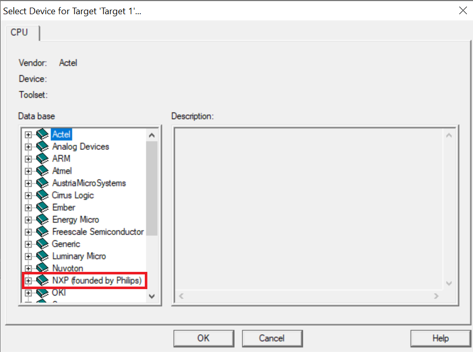
In the next window locate NXP (founded by Philips) tree and expand it.
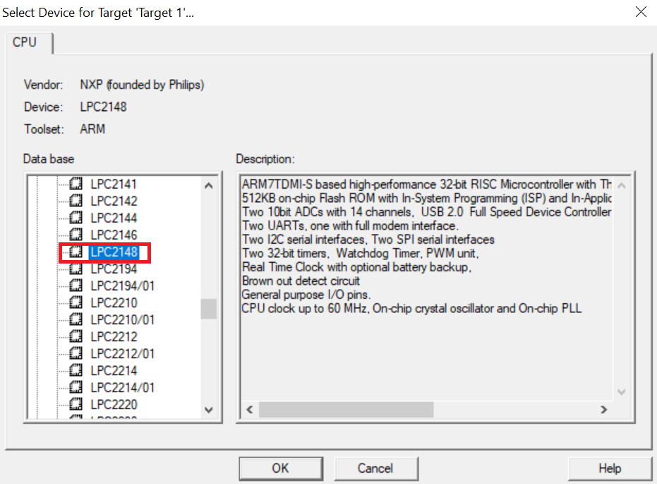
Now select target device as LPC2148 and click OK to continue.
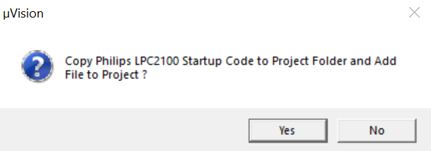
Click Yes to copy Startup.s file to project folder. This file configures stack, PLL and maps memory as per the configurations in the wizard.
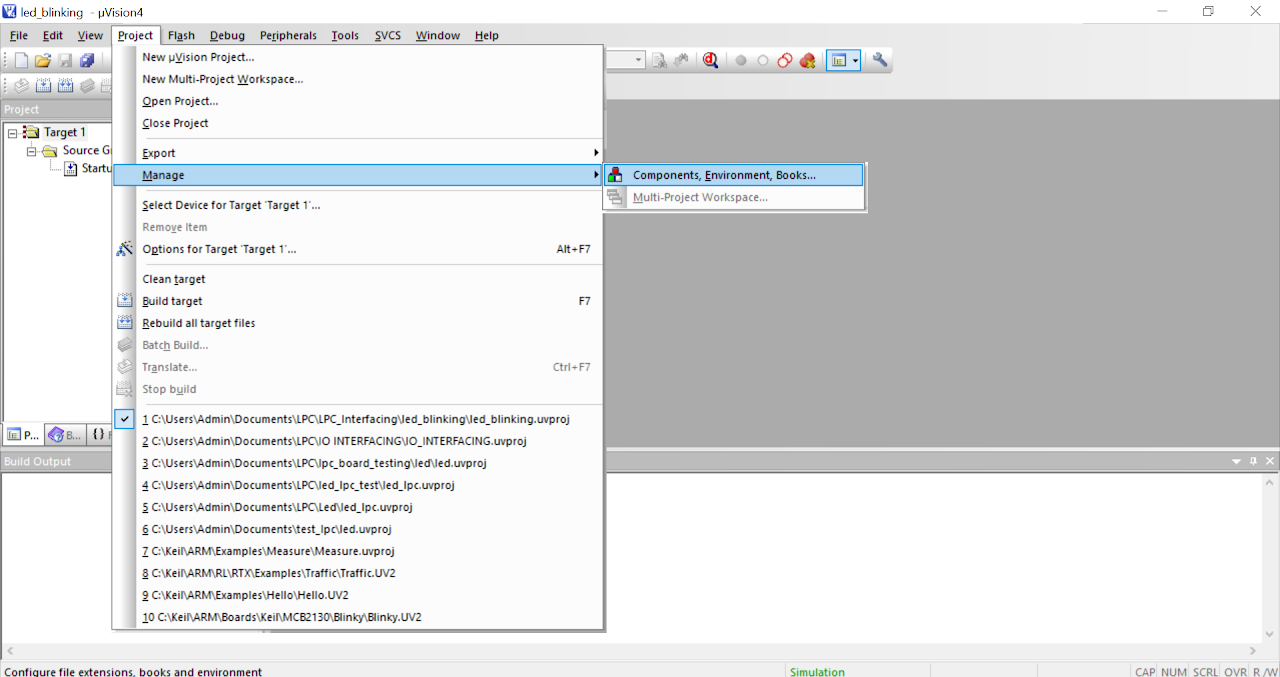
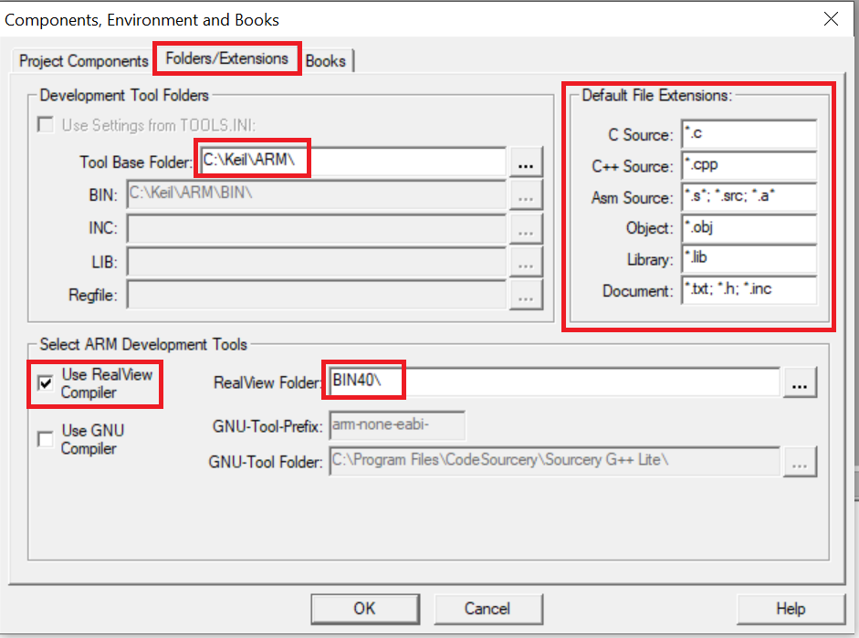
Now click Project>Manage>Components, Environments, Books from the main menu to ensure compiler settings.
In the Folders/Extensions tab ensure the compiler settings are as shown in the fig. below. If you have installed keil software at a different location then change Tool Base Folder location. Click OK to continue.
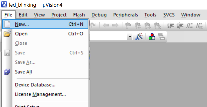
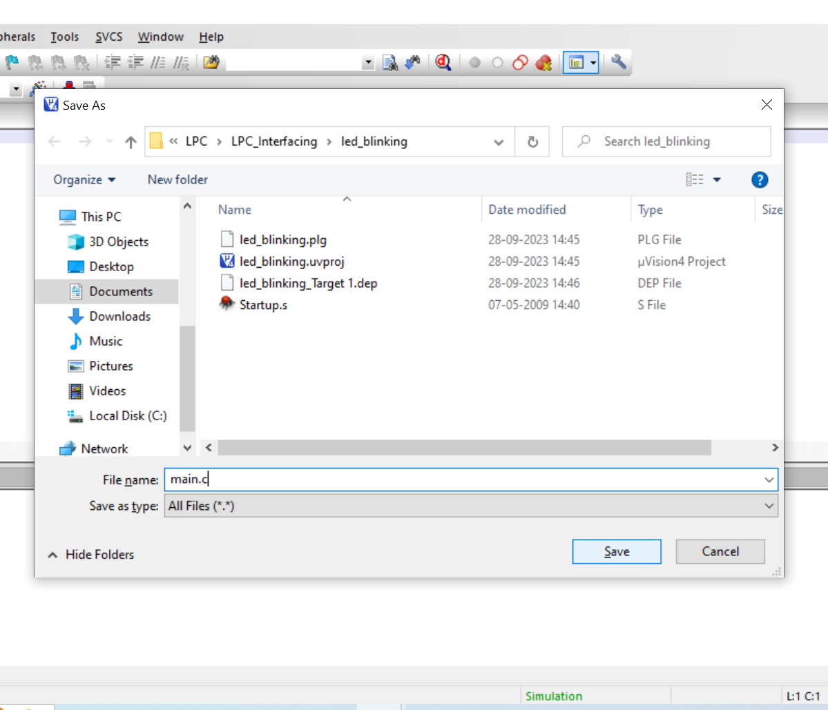
- Now click File>New to create a new file and save it as main.c
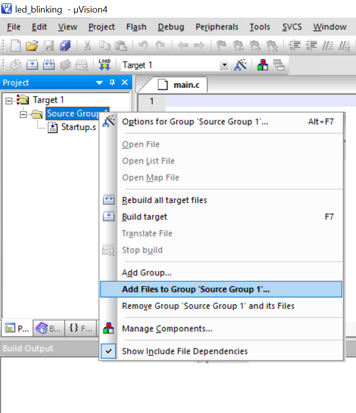
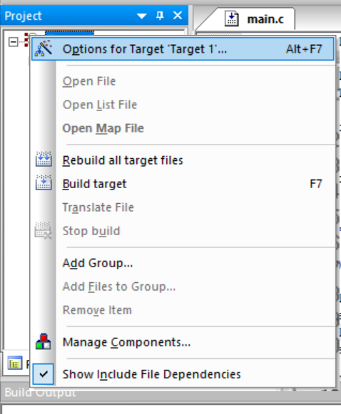
Now add “main.c” to the source group by right clicking on the Source Group 1 from the project explorer and select the highlighted option as shown in the fig. below.
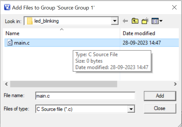
Select “main.c” file to be added and click ADD to continue.
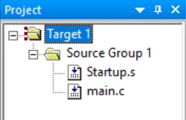
Observe that “main.c” file is added to the source group in the project explorer window.
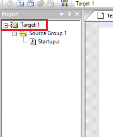
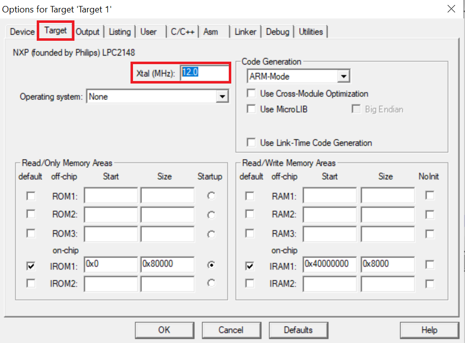
- Right click Target1 in the project explorer window and select the highlighted option as shown in the fig. below.
In the appearing window select the following:
Target tab and set Xtal. frequency as 12MHz.
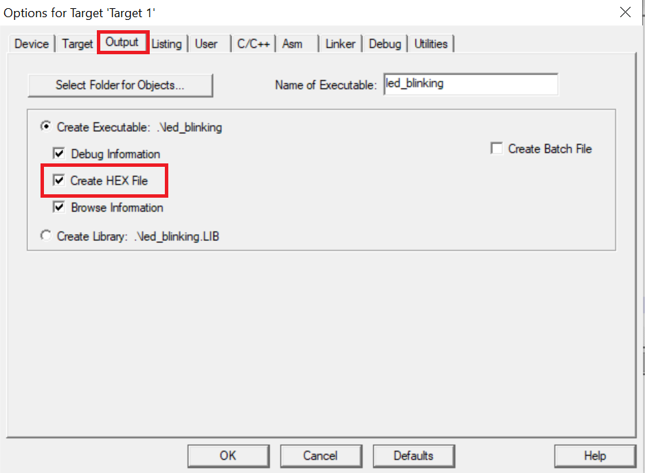
Output tab ensure that Create HEX File option is selected.
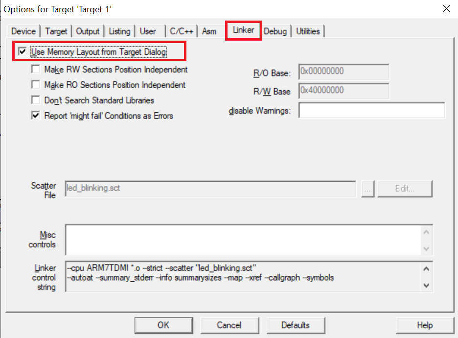
Linker tab ensure that the highlighted option is selected and click OK to continue.
Now since the project is almost setup we can start writing code in the “main.c” file that was created earlier. For demonstration purpose you can copy the following code and paste it in the “main.c” file. This code is written to blink LED on D1 on LPC2148 development board.
Copy the code given below into the main.c file and save the main.c file. You can also copy and paste the code from here into the file.
#include  <lpc214x.h>              //Includes LPC2148 register definitions

#define LED1_ON() IO1SET=(1<<16)     //Macro Functions to turn ON LED
#define LED1_OFF() IO1CLR=(1<<16)    //Macro Functions to turn OFF LED
void Delay(unsigned int);

int  main(void)
{
    PINSEL2 = 0x00000000;       // Enable GPIO on all pins
    IO1DIR = (1<<16);           // Set P1.16 as Output  to control LEDs
    while(1)
    {
        LED1_ON();
        Delay(100);
        LED1_OFF();
        Delay(100);
    }
}

void Delay (unsigned int ms)
{
    unsigned int i, j;
    for (j = 0; j < (ms / 10); j++)
    {
        for (i = 0; i < 60000; i++);
    }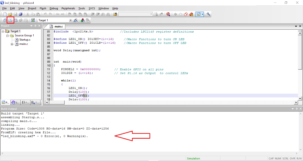
}- After saving the file click on build icon or press F7. You should be able to see the build output with 0 errors and warnings.
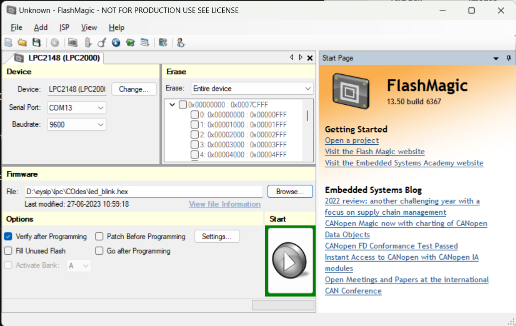
Now the hex file has been generated i.e. your program is compiled for uploading on the board. Open Flash Magic and do the following changes:
a. Change the Device to LPC2148
b. Select the Serial Port
c. Change the baud rate to 9600
d. Finally in the firmware section select the generated hex file.
e. In the erase section select entire device (refer the image below).
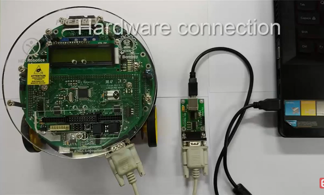
To upload the code do the following:
i. Connect a DB9 cable between the selected COMx port on your PC and the UART0 port on LPC2148 development board.
ii. Plug in an AC/DC 9V/1A supply to the development board and slide ON/OFF switch to ON position.
iii. Enter in to boot load mode by keeping the BOOT switch pressed and then press RESET switch.
iv. You should see LED D4 glowing which means board is now in programming mode.
- Click on Start in the Flash Magic tool. This will upload the code to the board.
- Once you have uploaded the code into board then exit the programming mode by pressing reset button once.
Output
Upon successfully running the project, the built-in LED Board will blink at a rate of 100ms. The blinking pattern demonstrates successful code execution and showcases the functionality of the board.
Conclusion
In this guide, you have learned how to blink the on-board LED of the LPC2148 board. By following the steps outlined here, you gained knowledge about configuring GPIO pins, writing code for microcontrollers, and uploading programs to the LPC2148 board. This basic example serves as a starting point for more advanced projects and exploration of the LPC2148 board's capabilities.