Using an Encoder with Raspberry Pi
Introduction
Problem Statement
Controlling position encoder using a Raspberry Pi.
Requirements
- Raspberry Pi
- Position encoder
- Jumper wires
Working
The position encoder, when integrated with a Raspberry Pi, enables precise and reliable position sensing and control. The Raspberry Pi utilizes its GPIO pins to interface with the position encoder and interpret the position information it provides. The position encoder generates electrical signals proportional to the position or displacement of the moving object, whether it's a rotary or linear motion.The Raspberry Pi reads and processes these signals to determine the current position accurately. It compares the desired position with the feedback obtained from the position encoder. If any deviation is detected, the control algorithm implemented in the Raspberry Pi adjusts the output signals to bring the object to the desired position. This closed-loop control system ensures precise positioning by continuously monitoring and adjusting the position based on the feedback obtained from the position encoder. The Raspberry Pi offers a flexible and powerful platform for implementing various control algorithms and applications that require accurate position sensing.
Circuit Diagram
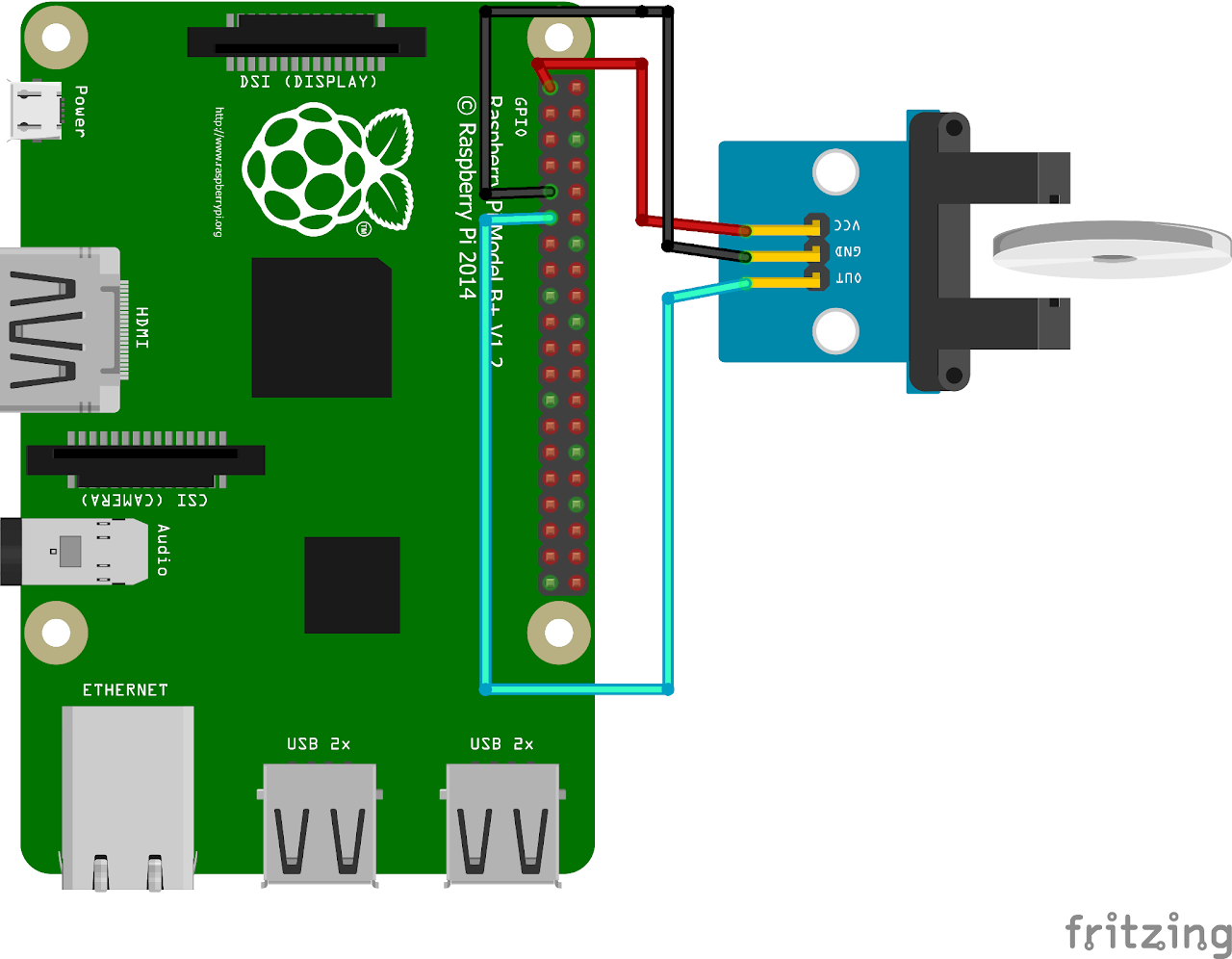
Follow the circuit diagram below to connect position encoder and Raspberry Pi:
- Connect the 3V3(PIN1) of Raspberry Pi to VCC of position encoder
- Connect the GND(PIN9) of Raspberry Pi to GND of position encoder
- Connect the DOUT of position encoder to GPIO17(PIN 11) of Raspberry Pi
Code
Now let's write the Python code for obtaining ECG values. Follow the steps below:
- Connect to your Raspberry Pi using VNC or Desktop environment.
- Launch the Geany Python IDE or open a text editor to write the code.
- Create a new file named
positionencoder.pyand save the following code into it - You can copy and paste the following code from here into the file.
import RPi.GPIO as GPIO

# Set GPIO mode and pins
GPIO.setmode(GPIO.BCM)
encoder_pin = 17
count = 0

# Set up interrupt handler

def encoder_interrupt(channel):
    global count
    # Increment the count
    count += 1
    print("Interrupt detected! Count:", count)

# Configure interrupt on rising edge
GPIO.setup(encoder_pin, GPIO.IN, pull_up_down=GPIO.PUD_UP)
GPIO.add_event_detect(encoder_pin, GPIO.RISING, callback=encoder_interrupt)

# Main program loop
try:
    while True:
        pass
except KeyboardInterrupt:
GPIO.cleanup()- After saving the file execute it by clicking on messenger like icon on geany editor or open terminal and navigate tothe folder you saved the file, execute it by typing python
encoder.py - After running the code swipe an object between receiver and transmitter of position encoder to verify the count and working of position encoder.
Output
The system initializes and starts counting the slots changed upon rotation of the encoder wheel. The count value is continuously printed on the terminal whenever a pulse is detected. Rotate the encoder shaft to observe changes in the count value. Each rotation or movement of the encoder generates pulses, resulting in a change in the count value.