Interfacing Servo Motor with the ATmega2560 Development Board
Introduction
A servo motor is a commonly used device in robotics and automation projects. It is capable of precise angular rotation and is widely used for controlling mechanical systems. In this guide, we will learn how to interface a servo motor with the ATmega2560 development board using embedded C code.
Requirements
To successfully complete this project, you will need the following components:
- ATmega2560 development board
- Micro USB cable
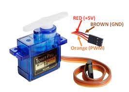
- Servo Motor
- Jumper Wires
Working
- Initialization: Set up the necessary hardware and software configurations to interface with the servo motor. This includes configuring the appropriate GPIO pin(s) and initializing any necessary timers or PWM modules.
- Pulse Width Modulation (PWM): Servo motors are typically controlled using PWM signals. PWM is a technique where the signal's pulse width is varied to control the position of the servo motor. The PWM signal is usually generated by a microcontroller's PWM module or by manually toggling a GPIO pin with the frequency of 50 Hz.
- Signal Control: To control the servo motor, you need to send specific control signals to it. These control signals typically consist of a series of PWM pulses. The duration (pulse width) of each pulse determines the position or angle to which the servo motor should rotate. For example, a pulse width of 1ms might correspond to 0 degrees, while a pulse width of 2ms might correspond to 180 degrees.
- Position Control: To set the position of the servo motor, you need to send a control signal with the appropriate pulse width. The servo motor receives this signal and moves its shaft to the corresponding position. The position is held until a new control signal is received.
- Feedback: Some servo motors have built-in position feedback mechanisms, such as potentiometers or encoders, to provide feedback on the motor's actual position. This feedback can be used to adjust the control signal and ensure accurate positioning of the servo motor.
- Continuous Operation: To continuously control the servo motor, you need to send periodic control signals at a specific frequency. Typically, a new control signal is sent every few milliseconds to maintain the desired position.
- By adjusting the pulse width of the control signal, you can control the servo motor's position and achieve precise angular control. The pulse width corresponds to a specific angle, allowing you to move the servo motor to the desired position or make it rotate continuously within a certain range.
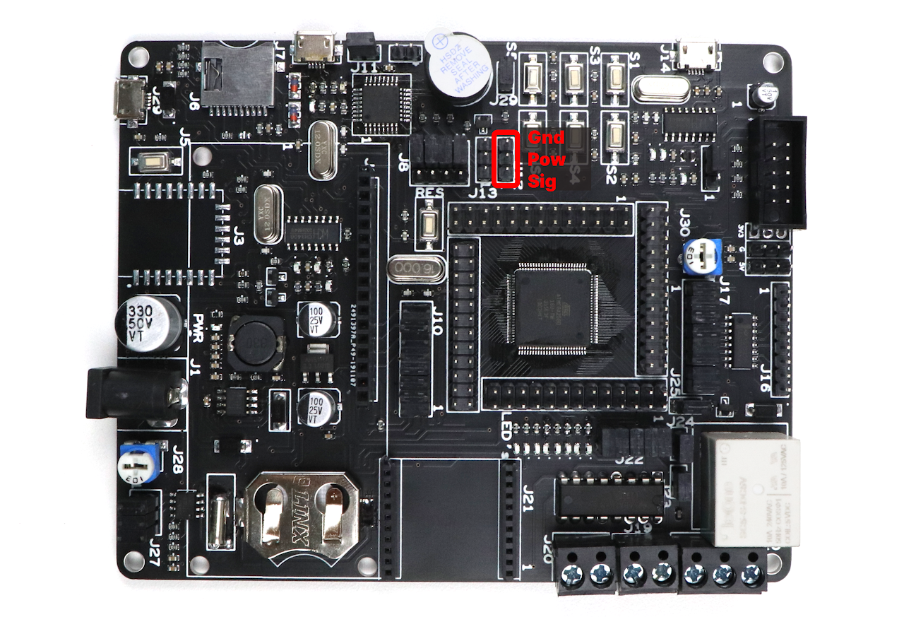
Component Placement
Code
- Open VS Code and paste the code into the file named servo.c
- To compile and convert this into hex run the following command in your terminal-
avr-gcc -Wall -g -Os -mmcu=atmega2560 -o servo.hex servo.cYou can download the code from here.
#ifndef F_CPU
#define F_CPU 16000000UL // set the CPU clock
#endif
#include <avr/io.h>     /* Include AVR std. library file */
#include <stdio.h>      /* Include std. library file */
#include <util/delay.h> /* Include Delay header file */

int main(void)
{
    DDRH |= (1 << PH3); /* Make OC4A pin as output */
    TCNT4 = 0;          /* Set timer4 count zero */
    ICR4 = 2499;        /* Set TOP count for timer4 in ICR4 register */
    /* Set Fast PWM, TOP in ICR1, Clear OC1A on compare match, clk/64 */
    TCCR4A = (1 << WGM11) | (1 << COM1A1);
    TCCR4B = (1 << WGM12) | (1 << WGM13) | (1 << CS10) | (1 << CS11);
    while (1)
    {
        OCR4A = 100; /* Set servo shaft at -90° position */
        _delay_ms(1500);
        OCR4A = 330; /* Set servo shaft at 0° position */
        _delay_ms(1500);
        OCR4A = 600; /* Set servo at +90° position */
        _delay_ms(1500);
   }
}- Now open AVRDUDES and from the Programmer (-c) dropdown select Any usbasp clone with the correct VID/PID
- In the Flash section, click on three dots and navigate to the desired hex file, and select it. Finally, click on Program to burn the hex file in the microcontroller.
Output
Upon successful upload and execution of the code, the servo motor will move to three different angles (-90°, 0°, and +90°) in a continuous loop. You will see the servo motor shaft rotating to these positions at a delay of 1.5 seconds between each movement.
Conclusion
Interfacing a servo motor with the ATmega2560 development board allows you to control the position and movement of mechanical systems. By following the steps outlined in this guide and understanding the provided code, you should be able to successfully interface and control a servo motor using the ATmega2560 development board. Experiment with different angle values and delays to achieve the desired servo motor movement for your specific project requirements.