Interfacing LCD with DE0 Nano FPGA
Introduction:
LCDs (Liquid Crystal Displays) are used for displaying status or parameters in embedded systems.
LCD 16x2 is 16 pin device that has 8 data pins (D0-D7) and 3 control pins (RS, RW, EN). The remaining 5 pins are for the supply and the backlight for the LCD. The control pins help us configure the LCD in command mode or data mode. They also help configure read or write mode and when to read or write.
LCD 16x2 can be used in 4-bit mode or 8-bit mode depending on the requirement of the application. In order to use it we need to send certain commands to the LCD in command mode and once the LCD is configured according to our needs, we can send the required data in data mode.
Problem Statement
Display message "Hi" on the LCD Display.
Requirements
- DE0 Nano FPGA
- Breadboard
- 16*2 LCD
- Potentiometer(10K ohm)
- Jumper wires
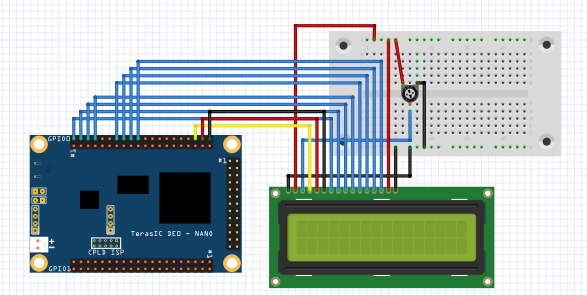
Circuit Diagram
- Connect VDD and positive of potentiometer
- Connect VSS and ground of potentiometer
- Connect VO to the output of potentiometer
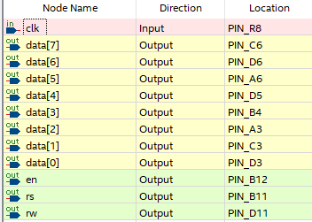
- Connect top part of the bread board to +5v and connect bottom part of the breadboard to ground. remaining LCD data and command pins according to the following figure:
Code
Copy and paste the following code into lcd.v or download it from here:
module lcd(clk,rs,rw,en,data);

input clk;
output reg rs,rw,en;
output reg [7:0]data;
reg [29:0] count=0;
integer m;

initial
begin
m=0;
end

always@(posedge clk)
begin
case(m)

0: begin
count=count+1;
data=8'h38;                 //initialization condition for 5x7 matrix
rs=0;
rw=0;
en=1;
if(count==10000000)         //10000000 is the count which gives a delay of 0.2sec
en=0;

end

1: begin

count=count+1;
data=8'h0E;                 //initialization condition for display on cursor off
rs=0;
rw=0;
en=1;

if(count==10000000)
en=0;
end

2: begin
count=count+1;
data=8'h01;                //initialization condition for clear LCD
rs=0;
rw=0;
en=1;
if(count==10000000)
en=0;

end
3: begin

count=count+1;
data=8'h06;             //initialization condition for shift cursor right
rs=0;
rw=0;
en=1;

if(count==10000000)
en=0;
end

4: begin

count=count+1;
data=8'h80;           //initialization condition for cursor at first line, position 1
rs=0;
rw=0;
en=1;

if(count==10000000)
en=0;
end

5: begin

count=count+1;
data=72;       //ASCII value of H
rs=1;
rw=0;
en=1;

if(count==10000000)
en=0;
end

6: begin

count=count+1;
data=105;   //ASCII value of i
rs=1;
rw=0;
en=1;

if(count==10000000)
en=0;

end

endcase
if(count==10000000)
begin
m=m+1;
count=0;
end

if(count<10000000)
m=m;

end
endmodule
Output
"Hi" in the first line will be displayed on the LCD. If you do not see the output then try adjusting the potentiometer.
Conclusion
By: Various applications can be implemented by interfacing an LCD with an FPGA, including embedded systems, human-machine interfaces, control panels, data visualization, and instrumentation displays. The FPGA's flexibility and programmability enable the customization of display functionalities, integration with other system components, and efficient data transfer for real-time display updates.
Interfacing an LCD with an FPGA provides a powerful solution for displaying information and creating user interfaces in digital systems. The FPGA's programmable logic, high-speed processing, and control capabilities enable the accurate and efficient control of the LCD display, offering versatile and customizable visual output for diverse applications.