Interfacing IR sensor with the LPC2148 Development Board
Introduction
Problem Statement
Requirements
To successfully complete this project, you will need the following components:
- LPC2148 Development board
- IR Sensor
- 16x2 LCD
- 2 USB cables, for power and programming.
Connections
This experiment involves connecting an external device, which is the IR sensor. Let's understand the connections for the IR sensor module:
The IR sensor module has three pins: OUT, GND, and VCC.
The OUT pin will be connected to pin 24 of Port 1, as specified in our experiment (you can choose any available pin on the board).
Connect the power pins of the IR sensor to the microcontroller's power pins.
Next for LCD we will be using the onboard slot available in the board. Ensure that the jumper connectors for LCD are connected properly. Plug in the LCD into the slot. LCD is connected to pins 16, 17, 18, 19, 20, 21 and 22 of Port 0.
Code
Open the Keil IDE and create a new project with name ir_sensor by clicking on project in the menu bar. (Refer the steps from Getting started page to create new project - do not skip any step from the process)
Copy the code given below into the main.c file and save the main.c file. You can also copy and paste the code from here into the file..
#include  <lpc214x.h>     //Includes LPC2148 register definitions

#define DATA_PORT() IO0SET=(1<<16)       //Function to select data port on LCD
#define READ_DATA() IO0SET=(1<<17)       //Function to select read operation on LCD
#define EN_HI() IO0SET=(1<<18)           //Function to Enable LCD

#define COMMAND_PORT() IO0CLR=(1<<16)     //Function to select command port on LCD
#define WRITE_DATA() IO0CLR=(1<<17)       //Function to select write operation on LCD
#define EN_LOW() IO0CLR=(1<<18)           //Function to disable LCD

unsigned char String1[16]={"IR Sensor"};

#define IR  (IO1PIN & (1<<24))


void Delay(unsigned char j)
{
    unsigned int  i;
    for(;j>0;j--)
    {
        for(i=0; i<60000; i++);
    }
}


void Delay_Small(unsigned char j)
{
    unsigned int  i;
    for(;j>0;j--)
    {
        for(i=0; i<1000; i++);
    }
}

unsigned char Busy_Wait()              //This function checks the busy status of LCD
{
    unsigned int temp=0;
    EN_LOW();
    COMMAND_PORT();
    READ_DATA();

    IO0PIN&=0xFF87FFFF;
    IO0DIR&=0xFF87FFFF;
    IO0PIN|=0x00400000;

    do{
        EN_HI();
        EN_LOW();
        EN_HI();
        EN_LOW();
        temp=IO0PIN;
    }
    while((temp & 0x00400000)==0x00400000);
    EN_LOW();
    WRITE_DATA();
    IO0DIR&=0xFF80FFFF;
    IO0DIR|=0x007F0000;
    return (0);
}

void LCD_Command(unsigned int data)           //This function is used to send LCD commands
{
    unsigned int temp=0;
    EN_LOW();
    COMMAND_PORT();
    WRITE_DATA();


    temp=data;
    IO0PIN&=0xFF87FFFF;
    IO0PIN|=(temp & 0xF0) << 15;

    EN_HI();
    EN_LOW();

    temp=data & 0x0F;
    IO0PIN&=0xFF87FFFF;

    IO0PIN|=(temp) << 19;
    EN_HI();
    EN_LOW();
    while(Busy_Wait());
    Delay(10);
}

void LCD_Data(unsigned int data)           //This function is used to send data to LCD
{
    unsigned int temp=0;
    EN_LOW();
    DATA_PORT();
    WRITE_DATA();
    temp=data;
    IO0PIN&=0xFF87FFFF;
    IO0PIN|=(temp & 0xF0) << 15;

    EN_HI();
    EN_LOW();
    temp=data & 0x0F;
    IO0PIN&=0xFF87FFFF;
    IO0PIN|=(temp) << 19;
    EN_HI();
    EN_LOW();
    Delay_Small(1);
}

void LCD_Init()
{
    LCD_Command(0x20);
    LCD_Command(0x28);
    LCD_Command(0x0C);
    LCD_Command(0x06);
}

void LCD_String(unsigned char *data)
{
    while(*data)
    {
        LCD_Data(*data);
        data++;
    }
}

int main(void)
{
    PINSEL0 = 0x00000000;       // Enable GPIO on all pins
    PINSEL1 = 0x00000000;
    PINSEL2 = 0x00000000;

    Delay(20);
    IO0DIR = (1<<22) | (1<<21) | (1<<20) | (1<<19) | (1<<18) | (1<<17) | (1<<16);       // Set P0.16, P0.17, P0.18, P0.19, P0.20, P0.21, P0.22 as Output
    IO1DIR = (1<<16);

    LCD_Init();
    LCD_Command(0x01);
    Delay(20);

    LCD_Command(0x80);
    LCD_String(&String1[0]);

    while(1)
    {
        if(IR == 0) {
            LCD_String("Obstacle Detcted");
        }
        Delay(100);
        LCD_Command(0x01);
    }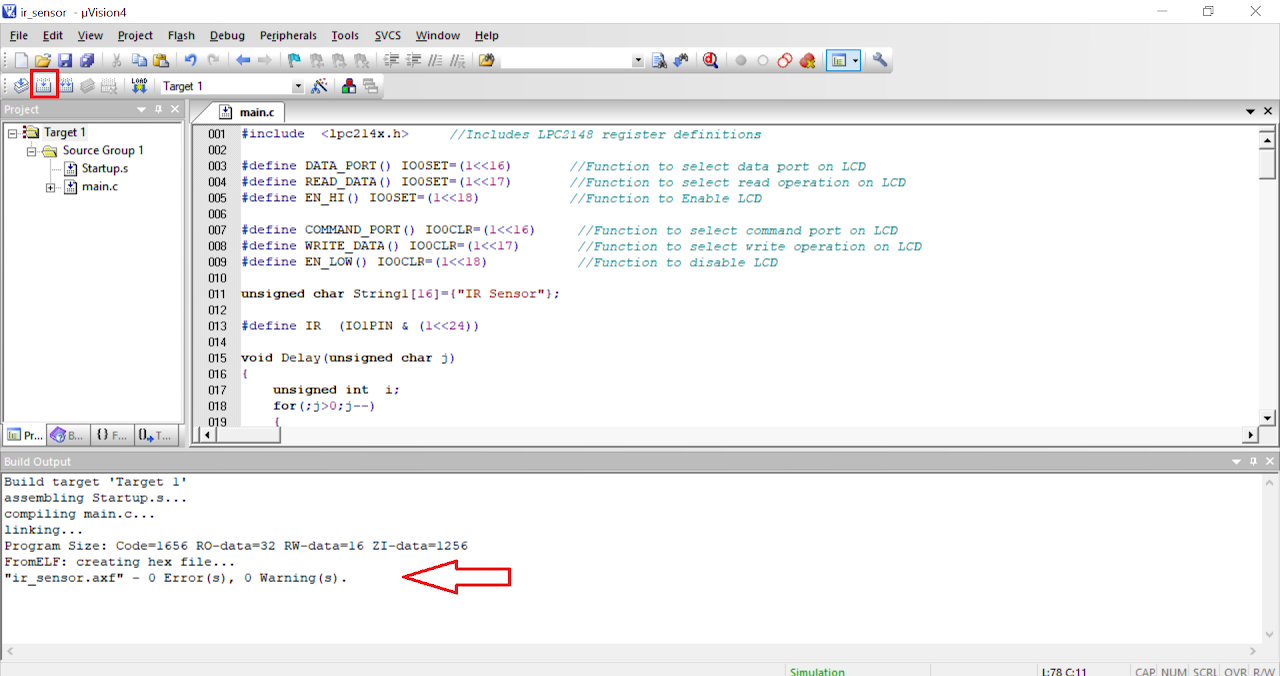
}- After saving the file click on build icon or press F7. You should be able to see the build output with 0 errors and warnings.
Now the hex file has been generated i.e. your program is compiled for uploading on the board. Open Flash Magic and do the following changes:
a. Change the Device to LPC2148
b. Select the Serial Port
c. Change the baud rate to 9600
d. Finally in the firmware section select the generated hex file.
e. In the erase section select entire device (refer the image below).
To upload the code do the following:
i. Connect a DB9 cable between the selected COMx port on your PC and the UART0 port on LPC2148 development board.
ii. Plug in an AC/DC 9V/1A supply to the development board and slide ON/OFF switch to ON position.
iii. Enter in to boot load mode by keeping the BOOT switch pressed and then press RESET switch.
iv. You should see LED D4 glowing which means board is now in programming mode.
Click on Start in the Flash Magic tool. This will upload the code to the board.
Once you have uploaded the code into board then exit the programming mode by pressing reset button once.
Output
Upon successfully running the project, the LCD connected to LPC2148 development board will display "obstacle detected" whenever there will be something in front of IR sensor.
Conclusion
In this guide, you have learned how to interface an IR sensor with the LPC2148 development board. By following the steps outlined here, you gained knowledge about connecting the IR sensor, reading its output, and performing actions based on the detected infrared signals. This basic example serves as a starting point for more advanced projects involving remote control systems, obstacle detection, and other applications using the LPC2148 board and IR sensors.